• Warning!!

    Riding a tuned or deristricted EMTB is not a trivial offence and can have serious legal consequences. Also, many manufacturers can detect the use of a tuning device or deristricting method and may decline a repair under warranty if it was modified from the intended original specification. Deristricting EMTB's can also add increased loads for motors and batteries. Riding above the local law limit may reclassify the bike as a low-powered bike, requiring insurance, registration and a number plate.

    Be aware of your local country laws. Many laws prohibit use of modified EMTB's. It is your responsibility to check local laws. Ignoring it, has potential implications to trail access, and risk of prosecution in the event of an accident.

    UK Pedelec Law

    Worldwide Laws

    We advise members great caution. EMTB Forums accepts no liability for any content or advice given here. 


Derestricting bosch smart system

Uktonyb77

New Member
Feb 19, 2023
34
24
Uk
So this is where my confusion was early in the conversation . Why would I need an electromagnet if I already have either a current speed sensor ( factory fitted in frame ) or alternatively as you’ve said relocate my current in frame speed sensor with the reed switch taking its place at the wheel I’m assuming where the speed sensor was housed originally…..so my question as earlier posts ; why would I need an electromagnet as you guys had mounted in your motor area at all if my particular bike build isn’t looking to sense a rim magnet type of sensor ??

Surely for a system which simply has magnet on the rotor with speedsensor built in the frame there wouldn’t be a need for the electromagnet at all or am I missing something entirely in how your device actually works ?

Thx again
Tony
 

megabobra

Active member
Jul 24, 2022
266
268
Australia
So this is where my confusion was early in the conversation . Why would I need an electromagnet if I already have either a current speed sensor ( factory fitted in frame ) or alternatively as you’ve said relocate my current in frame speed sensor with the reed switch taking its place at the wheel I’m assuming where the speed sensor was housed originally…..so my question as earlier posts ; why would I need an electromagnet as you guys had mounted in your motor area at all if my particular bike build isn’t looking to sense a rim magnet type of sensor ??

Surely for a system which simply has magnet on the rotor with speedsensor built in the frame there wouldn’t be a need for the electromagnet at all or am I missing something entirely in how your device actually works ?

Thx again
Tony

Yes you're exactly right: applying a the electromagnet to your setup is more convoluted than it needs to be, which is why I suggested dropping the electromagnet, cutting your speed sensor and pushing the ardunio in the middle of it. Only go own the electromagnet route if either you don't want to cut the speed sensor and/or don't want to buy a spare speed sensor. :)
 

X-Tream

New Member
Mar 19, 2023
5
1
Finland
Hello,

Thank you Megabobra and Sander for your efforts on derestricting Bosch Smart System bikes with rim magnets.

I'm currently planning on doing this to my bike, but I have a few questions. Also, as a disclaimer I must say that this is not my area of expertise so I apologice if some of my questions seem odd.

Page 6 Megabobra you provide the instructions on how to do this with electromagnet. Later on the thread you and Sander talk about replacing this with enameled copper wire for e.g. this (0.3mm wire, diameter 25mm, about ~10m of wire -> this should make the coil resistance ~15ohms(?)). My understading is that this would be the preffered way of doing this instead of the electromagnet? If so, do I also need a 0.5watt 10ohm resistor in a 5v system? Is it possible to get a wiring schematic for this build also? Just so that I don't mess things up. :)

I was also wondering would you Sander be willing to share the files required to print the 3D case you made? :)
I can ofcourse use an alternative 3D case for Arduino, but to pay respect for the project/maker it would be nice to print it with Megabobras name.

Once again thanks to both of you.
 

Sander

Member
Dec 29, 2022
56
29
NL
Hello,

Thank you Megabobra and Sander for your efforts on derestricting Bosch Smart System bikes with rim magnets.

I'm currently planning on doing this to my bike, but I have a few questions. Also, as a disclaimer I must say that this is not my area of expertise so I apologice if some of my questions seem odd.

Page 6 Megabobra you provide the instructions on how to do this with electromagnet. Later on the thread you and Sander talk about replacing this with enameled copper wire for e.g. this (0.3mm wire, diameter 25mm, about ~10m of wire -> this should make the coil resistance ~15ohms(?)). My understading is that this would be the preffered way of doing this instead of the electromagnet? If so, do I also need a 0.5watt 10ohm resistor in a 5v system? Is it possible to get a wiring schematic for this build also? Just so that I don't mess things up. :)

I was also wondering would you Sander be willing to share the files required to print the 3D case you made? :)
I can ofcourse use an alternative 3D case for Arduino, but to pay respect for the project/maker it would be nice to print it with Megabobras name.

Once again thanks to both of you.
Hi X-team,
A friend of mine designed and printed the case. I'll ask him to share me file 😏
 

megabobra

Active member
Jul 24, 2022
266
268
Australia
Hello,

Thank you Megabobra and Sander for your efforts on derestricting Bosch Smart System bikes with rim magnets.

I'm currently planning on doing this to my bike, but I have a few questions. Also, as a disclaimer I must say that this is not my area of expertise so I apologice if some of my questions seem odd.

Page 6 Megabobra you provide the instructions on how to do this with electromagnet. Later on the thread you and Sander talk about replacing this with enameled copper wire for e.g. this (0.3mm wire, diameter 25mm, about ~10m of wire -> this should make the coil resistance ~15ohms(?)). My understading is that this would be the preffered way of doing this instead of the electromagnet? If so, do I also need a 0.5watt 10ohm resistor in a 5v system? Is it possible to get a wiring schematic for this build also? Just so that I don't mess things up. :)

I was also wondering would you Sander be willing to share the files required to print the 3D case you made? :)
I can ofcourse use an alternative 3D case for Arduino, but to pay respect for the project/maker it would be nice to print it with Megabobras name.

Once again thanks to both of you.

Hi Xtream,
The resistor is only required if you need to increase the overall resistance of your wound copper wire. You really need to be able to measure its resistance before use - do you have a means of doing so with a multimeter or similar?

If not, you might find it easier to use the off the shelf magnet I originally linked. I'm still using this in my setup as I just haven't had the time to switch to the copper coil. Once you find the right location and get the magnet to stay there, the commercial electromagnet is fine. Winding your own is just a bit more forgiving with placement given it's flexibility and shorter height.

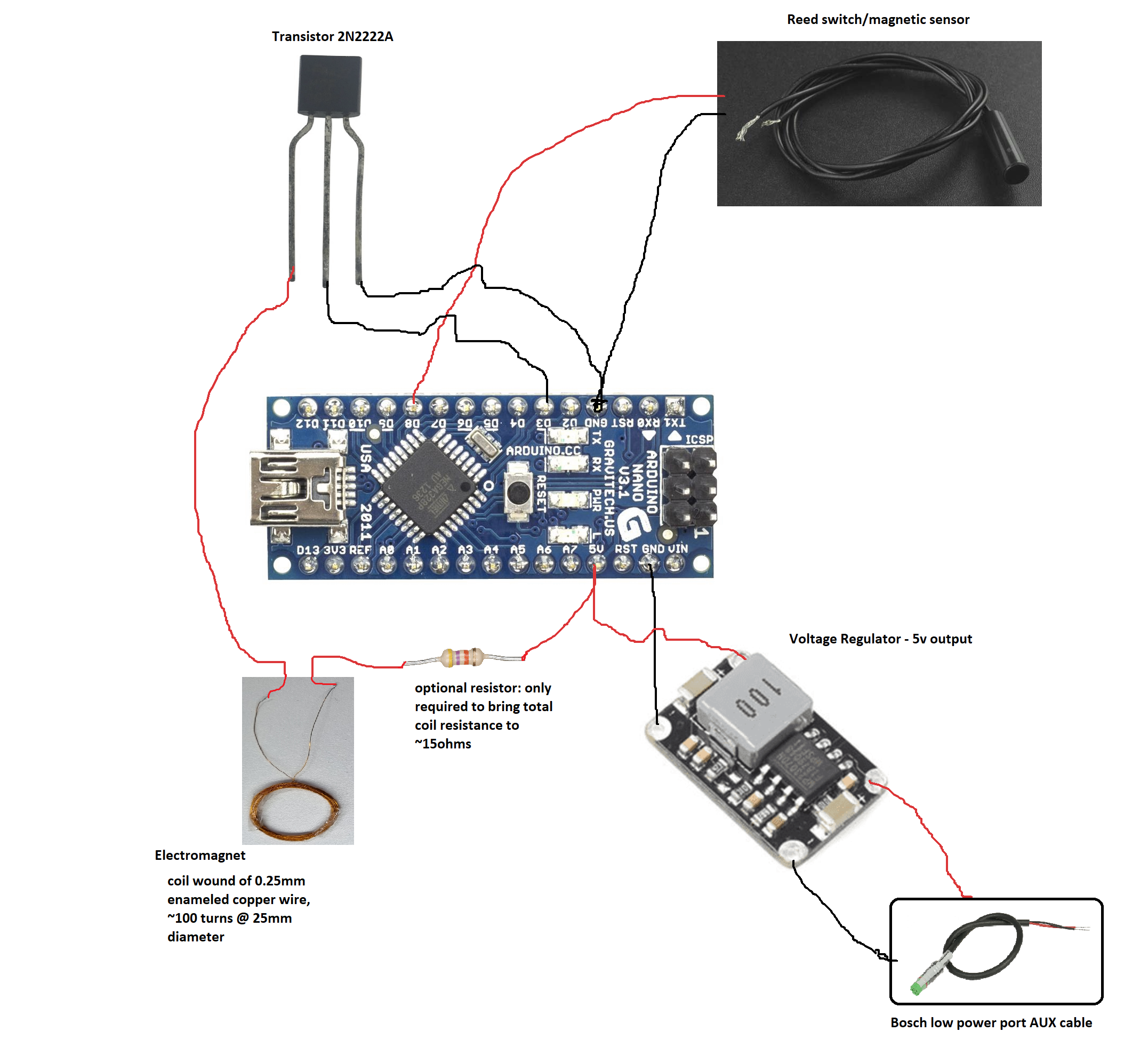
Quick new schematic attached for the coil.

coil.png
 
Last edited:

X-Tream

New Member
Mar 19, 2023
5
1
Finland
Thank you Megabobra and Sander for your comments.

I do have a multimeter so I'm able to measure the resistance. I might just buy the electromagnet as a backup plan, however I think it will be hard to make it fit into my bike as there is not a lot of free space.

And thank you for going the extra mile in doing the new schematic. I really appreciate it.
 

Hankfury

Member
Mar 15, 2021
4
1
Manchester
Really really cool review mate ! thanks for this !

I bought the Simplek pro Stealth Edition ( sIMPLEK have a serious reputation in germany apparently) can't wait to test it ! If it's doesn't work well i think i buy the speedfun because its 2 less expensive

View attachment 98840

Do you need an activation everytime you start the smart system ?
And i think yes majority of error is with the Bosch app flow, I will uninstall it too when I receive the module

I keep you in touch with some 524001 error &


simplek-pro-tuning-modul-bosch-smart-system-bes3
I’ve run this for 4000k but it has just been detected. Bike has been reset… but at same time it automatically gets latest updates… I’m gonna give it another go but the limpmode you are supposed to get back on is useless if you are in the back of beyond. Bosch should cut power in half rather than the useless pulse system it currently defaults to.
 

Orloaf

New Member
Mar 18, 2023
2
0
Deutschland
Hi, if you don't want to cut the cable you need this here ;) Seems to be a 3D printed female version of the connector. It's from an german tuner. Can somebody told me if the aux plug is the same coding (dimensions) like the speed sensor plug. If so, i can try to reverse engineer the the female connector , and share the slt.
1679298353104.png

1679311442361.png

 
Last edited:

X-Tream

New Member
Mar 19, 2023
5
1
Finland
Megabobra could you please advice me on the new code you provided us.

I was just wondering that is there a reason why the variables and methods (setup and loop) are declared multiple times?

If this is not intended would this be something you could have a look at? Below you can find a version where the duplicate variables and methods have been removed, but it might be good if you would check that there is nothing missing etc?

Thank you.
 

Attachments

  • Code.txt
    2.8 KB · Views: 153

Orloaf

New Member
Mar 18, 2023
2
0
Deutschland
Megabobra could you please advice me on the new code you provided us.

I was just wondering that is there a reason why the variables and methods (setup and loop) are declared multiple times?

If this is not intended would this be something you could have a look at? Below you can find a version where the duplicate variables and methods have been removed, but it might be good if you would check that there is nothing missing etc?

Thank you.
Yes you are right, everything is double.
 

megabobra

Active member
Jul 24, 2022
266
268
Australia
Megabobra could you please advice me on the new code you provided us.

I was just wondering that is there a reason why the variables and methods (setup and loop) are declared multiple times?

If this is not intended would this be something you could have a look at? Below you can find a version where the duplicate variables and methods have been removed, but it might be good if you would check that there is nothing missing etc?

Thank you.
You're right, my mistake. Must have copy/pasted incorrectly when creating then file for the new version; you can just delete the first 28lines. I've updated the file in the tutorial, as well a copy here. Confirm your update above is correct, but just ensure the two #define lines are first before the MultiplierIn definition.
 

Attachments

  • Rampup Code 210323.txt
    2.8 KB · Views: 190

Uktonyb77

New Member
Feb 19, 2023
34
24
Uk
Curiosity in your new code where you changed the system to start working at a preset of 6kph I think you had mentioned. Why would you not set this preset to say 20kph before the multiplier effect kicks in so you get the most true to original power curves in all the different ride modes. Maybe you tried already perhaps ??? I know you mentioned this preset start speed being introduced due to the motor acting weirdly on slow steep low speed climbs. So my thinking is if multiplier only introduced when approaching the speed limitation say can the multiplier get introduced here ???

Again just to confirm 100% mega that I don’t need to worry about the electromagnet part of the design at all if I’m on a simple disc magnet setup ?

Thx

Tony.
 

megabobra

Active member
Jul 24, 2022
266
268
Australia
Curiosity in your new code where you changed the system to start working at a preset of 6kph I think you had mentioned. Why would you not set this preset to say 20kph before the multiplier effect kicks in so you get the most true to original power curves in all the different ride modes. Maybe you tried already perhaps ??? I know you mentioned this preset start speed being introduced due to the motor acting weirdly on slow steep low speed climbs. So my thinking is if multiplier only introduced when approaching the speed limitation say can the multiplier get introduced here ???

Again just to confirm 100% mega that I don’t need to worry about the electromagnet part of the design at all if I’m on a simple disc magnet setup ?

Thx

Tony.
Hi Tony,
I introduced the multiplier at a low speed because I want as little time as possible spent in the original un-multiplied state. One of my primary aims was to maintain usability of all the ride stats, odometer, trip meter, max/average speed etc, simply using the multiplier to scale those numbers. The longer you're in the un-multiplied state, the less effective that scaling will be.

Plus, 6kph is a speed you're unlikely to be falling above/below very frequently. If you set this to 20kph, you're likely to be tripping below this speed and setting the scaling back to 1:1 until you increase speed again. Not sure, but I'd expect this oscillation between multiplied and un-multiplied is more likely to tip off the motor, which would see it as a frequently changing relationship between pedal power in + motor power out and the resulting speed.

You can certainly give it a try though, just change that millisecond value to represent something more representative of 20kph and see how it goes. You can always change it back!

As for the need for the electromagnet: I'm not sure about this as I haven't been able to try it, my Voima is rim magnet only, so you'll be treading new ground. Assuming you're planning on using the existing speed sensor and putting the Ardunio between the motor and the wheel, then make sure you check the resistance values of the speed sensor as I mentioned earlier. Assuming that's OK, then give it a try. If it doesn't work, reinstall and/or replace the standard speed sensor and proceed with the electromagnet approach, with the electromagnet up against the speed sensor.
 

Uktonyb77

New Member
Feb 19, 2023
34
24
Uk
Thx for response mega . When you refer to the electromagnet up against the speed sensor in my setup do you infact mean the reed switch ?

I thought the electromagnet on your design ( located back of motor housing ) where you have the rim magnet type setup was there to introduce a magnetic field of sorts which your setup requires to function correctly.

I’m assuming in a disc magnet setup this need / requirement for an electromagnet creating the magnetic field isn’t required ???

From my little knowledge the reed switch is a simple open / closed circuit scenario which is triggered when the disc magnet passes the reed switch. By then introducing a multiplier ( timing change variable ) here we are effectively then manipulating the reported speed .

So as I understand things if it works ofcourse is my original speed sensor will read the disc magnet passing by it and send the signal direct to the ardinio board which then has the code running on it which manipulates the resulting output by the 1.4 or whatever programmed multiplier. The manipulated output is then fed into the speed sensor port on the Bosch motor.

Please pull me up if I’m understanding things wrong mega :)

Thx
 

Uktonyb77

New Member
Feb 19, 2023
34
24
Uk
& not to be thick but if powering from the LPP port does this mean we are able to turn device on / off via the light button on the smart system ? Thx again
 

megabobra

Active member
Jul 24, 2022
266
268
Australia
Thx for response mega . When you refer to the electromagnet up against the speed sensor in my setup do you infact mean the reed switch ?

I thought the electromagnet on your design ( located back of motor housing ) where you have the rim magnet type setup was there to introduce a magnetic field of sorts which your setup requires to function correctly.

I’m assuming in a disc magnet setup this need / requirement for an electromagnet creating the magnetic field isn’t required ???

From my little knowledge the reed switch is a simple open / closed circuit scenario which is triggered when the disc magnet passes the reed switch. By then introducing a multiplier ( timing change variable ) here we are effectively then manipulating the reported speed .

So as I understand things if it works ofcourse is my original speed sensor will read the disc magnet passing by it and send the signal direct to the ardinio board which then has the code running on it which manipulates the resulting output by the 1.4 or whatever programmed multiplier. The manipulated output is then fed into the speed sensor port on the Bosch motor.

Please pull me up if I’m understanding things wrong mega :)

Thx

You're understanding correctly, yes. The untested part is interfacing the arduino direct to the motor through the speed sensor port. This is where you need to check the resistance of the original speed sensor to confirm if it's just a simple reed switch. If it is, then yes I think it will be OK just to wire up the interface from ardunio to motor across the transistor, where rather than allowing current to flow to the electromagnet, you'll instead simply be closing a circuit like the speed sensor would do.

I made some comments about it here with the wiring diagram: Derestricting bosch smart system
To confirm, if you're trying this approach, you don't need the electromagnet but you need either a new reed switch or the original speed sensor at the wheel with disc magnet.
 

megabobra

Active member
Jul 24, 2022
266
268
Australia
& not to be thick but if powering from the LPP port does this mean we are able to turn device on / off via the light button on the smart system ? Thx again

Unfortunately not. The LPP is different to the lighting ports. So the LPP is powered at all times when the bike is on. You can't really afford to turn off the arduino once in place anyway, as then you would be receiving no speed reading at all.

The easiest way I've found to disable mine when required is simply to unplug from the LPP and reinstall the rim magnet.
 

stratosa

Member
Apr 17, 2020
42
14
GREECE
Curiosity in your new code where you changed the system to start working at a preset of 6kph I think you had mentioned. Why would you not set this preset to say 20kph before the multiplier effect kicks in so you get the most true to original power curves in all the different ride modes. Maybe you tried already perhaps ??? I know you mentioned this preset start speed being introduced due to the motor acting weirdly on slow steep low speed climbs. So my thinking is if multiplier only introduced when approaching the speed limitation say can the multiplier get introduced here ???
Hi, i had a similar idea, Please see post 147
 

X-Tream

New Member
Mar 19, 2023
5
1
Finland
Has anyone had issues opening the low power port via Bosch service dealer? My understanding is that this can't be done via Flow app?
I got a reply from Bosch service dealer that I need to require a permission from the bike manufacturer as this is something that they can't do directly. This is, and i quote "an official response from Bosch".
They also informed me that Bosch requires to know what I'm going to connect to the port. The service dealer pressumes this has something to do with the warranty. Are there some actual use cases for the LPP?
 

Uktonyb77

New Member
Feb 19, 2023
34
24
Uk
You mean this post “”Hi and congratulations. I was wondering if it is possible to program Arduino in a way that it sends the real frequency that it receives down to 0.4 sec between pulses and keep sending a signal to electromagnet every 0.4 sec if the real value is less than that.””

Guess only way would be test it. All my parts have arrived now so it’s just assembly , fit then test. If I get error’s I will ofcourse report back to the forum as to what issues encountered and if all working great I will also report as such. I get on well with my local LBS so won’t be an issue getting stuff reset etc if there’s diagnostic issues.

Before doing anything mega I shall just ask your advice as to the resistance measured across the standard Bosch speed sensor as integrated on the frame currently .

Thx again :)
 

BeBiker

Active member
Aug 26, 2020
700
421
Belgium
Hi Xtream,
The resistor is only required if you need to reduce the overall resistance of your wound copper wire. You really need to be able to measure its resistance before use - do you have a means of doing so with a multimeter or similar?

If not, you might find it easier to use the off the shelf magnet I originally linked. I'm still using this in my setup as I just haven't had the time to switch to the copper coil. Once you find the right location and get the magnet to stay there, the commercial electromagnet is fine. Winding your own is just a bit more forgiving with placement given it's flexibility and shorter height.

Quick new schematic attached for the coil.

View attachment 109626
The Arduino Nano accepts --> 12V at the Vin pin, so you don't need the voltage converter.
The newer designs are stable at that voltage.

Best to also power the coil from the 12V in that case, with a modified limiting resistor.
 

Zimmerframe

MUPPET
Subscriber
Jun 12, 2019
14,060
20,859
Brittany, France
The ports and cables have already been mentioned in this thread, but here's some more information/reminder (taken from elsewhere as they also provided some extra information in German which will make it easier for some).

Smart System Ports.png


Smart System Cables.png


Some bikes will have LPP and HPP or lights enabled by default.

Some manufactures theoretically can/will have locked out access to the LPP/HPP and it won't always be possible to enable these.

I think the display/kiox port has two data pins and two for a power circuit, red and black in the cable (5v I think, but could be 12v like all the other ports and step down to 5v at the Kiox ?). Not sure if you could also splice/use splitter/take off from here as you're only pulling a tiny current.
 
Last edited:

BeBiker

Active member
Aug 26, 2020
700
421
Belgium
On my GEN4 BES3 smart bike, the LPP port is used for the speed sensor.
The HPP can be enabled/configured as LPP or HPP.
The ports for front light and rear light can be configured as 6V or 12V.
Enabling the front light in the dealer software disables 10% of the battery capacity as Stvzo spare.
 

Zimmerframe

MUPPET
Subscriber
Jun 12, 2019
14,060
20,859
Brittany, France
Enabling the front light in the dealer software disables 10% of the battery capacity as Stvzo spare.
By law if you have lights activated the system has to be configurable to ensure that there will be enough reserve to power the lights for 2 hours.

The reserve on the Bosch (for lights) is dealer configurable between 3% and 18% - I believe the default setting is 10%.

Likewise, if you have eshift or similar configured that also keeps a reserve. Presumably, if you have ABS enabled, that will also keep a reserve.

There was a theory that if you enabled the LPP or the HPP, then there may also be a reserve for these, but I've not tried it or read of anyone else checking it.
 

stratosa

Member
Apr 17, 2020
42
14
GREECE
Before doing anything mega I shall just ask your advice as to the resistance measured across the standard Bosch speed sensor as integrated on the frame currently .
Hi, do not worry about anything, just bybass the adruino between the speed sensor and the speed sensor port.
 

Uktonyb77

New Member
Feb 19, 2023
34
24
Uk
I can’t bypass the ardruino in the setup I’m trying achieve. I’m trying with original Bosch in frame ( lower stay ) speed sensor and disc magnet. I don’t have the rim magnet on my bike so I’m trying a different setup just a basic version I guess of what all the 3rd party chips pretty much do.
 

megabobra

Active member
Jul 24, 2022
266
268
Australia
Has anyone had issues opening the low power port via Bosch service dealer? My understanding is that this can't be done via Flow app?
I got a reply from Bosch service dealer that I need to require a permission from the bike manufacturer as this is something that they can't do directly. This is, and i quote "an official response from Bosch".
They also informed me that Bosch requires to know what I'm going to connect to the port. The service dealer pressumes this has something to do with the warranty. Are there some actual use cases for the LPP?

My dealer was able to activate it when they connected through the USB service port on the handlebar controller. No issues at all.
 

sam952802

New Member
Mar 21, 2023
4
4
Italia
Hello, everybody!

Last week Eplus released his new speed unlocker for rim magnet. After months of waiting i was so happy until i found out they charge over 500€ and you have to send them your bike, because it's a "custom" installation. So i decided to make my own version and i bought all the the stuff (MCU, battery, transistor in order to drive the coil and so on).

Before starting i said " Ok, let me first figure out how the original sensor reacts to a magnetic field which is not the original one, let's make a simple test". So i removed the rim magnet and placed a small neodimium magnet on the front chainring (facing the motor). I turned on the bike and all was working. At 40 kmph Kiox displays fabout 15 kmph and motor keeps powering no stop.

At this point, surfing the net and I came up here and i found out megabora already had and successfully implemented my starting idea (Good work! :) ).

Did anyone else try to put a magnet on the front chainring? I mean, i had no error until now but it seems too easy... i won't be suprised to get some error in the future.
 

EMTB Forums

Since 2018

The World's largest electric mountain bike community.

559K
Messages
28,313
Members
Join Our Community

Latest articles


Top