• Warning!!

    Riding a tuned or deristricted EMTB is not a trivial offence and can have serious legal consequences. Also, many manufacturers can detect the use of a tuning device or deristricting method and may decline a repair under warranty if it was modified from the intended original specification. Deristricting EMTB's can also add increased loads for motors and batteries. Riding above the local law limit may reclassify the bike as a low-powered bike, requiring insurance, registration and a number plate.

    Be aware of your local country laws. Many laws prohibit use of modified EMTB's. It is your responsibility to check local laws. Ignoring it, has potential implications to trail access, and risk of prosecution in the event of an accident.

    UK Pedelec Law

    Worldwide Laws

    We advise members great caution. EMTB Forums accepts no liability for any content or advice given here. 


MEGABOBRA: Bosch Smart System Derestriction for Rim Magnet - DIY Project with Support

Striveon

New Member
May 24, 2024
1
0
California
Have a 2024 Canyon Strive On with Bosch CX race motor rim magnet. Confirming your device will work? Love to have one so much more fun without the cut off.
Thanks
 

Peacepirate

New Member
May 22, 2024
8
0
Cologne
You can leave that line of code in place and simply make no connection to Pin4.
Hey there,
when i tried the first time to test your code it didnt worked out but i wanted to check everything before proclaiming that and be sure that this wasnt caused by a wrong edited code. i dont need a variable multiplier but just a fixed value of 2.0 and i dont need a setup mode either so i deleted that part. To exclude these potential sources of errors i uploaded your code again with the changes you talked about:

#define REED_SENSOR_PIN 2
#define SETUP_PIN 6
#define ELECTROMAGNET_PIN 7
#define REDLED_LOWPRESSCOUNT_PIN 5
#define A1A 4
#define A1B 3


byte ButtonState;
byte LastButtonState;
byte Trigger = HIGH;
byte SetupState;

double LastPress = 0;
double CurrentPress = 0;
double EndMagnet = 0;
double MagnetDuration = 0;
double Delta;
double DeltaStatic;
double ActivateMagnetStart = 0;
double ActivateMagnetTemp = 0;
double MultiplierOut = 1;
double MagnetOnTime = 0;
double MultiplierCutOff = 1398; //1398 = 6kph/3.5mph

int Pressed = 0;
int PressCount = 0;
int MagnetSwitch = 0;
int MagnetOn = 0;


////////////////////
//change this MultiplierOut to alter max assistance speed. MultiplierOut 1.4 gives: 25kph * 1.4 = 35kph new max assitance
double MultiplierIn = 2.0;
double SetupDelay = 513;
double SetupWidth = 47;


void setup() {

pinMode(ELECTROMAGNET_PIN, OUTPUT);
pinMode(REED_SENSOR_PIN, INPUT_PULLUP);
pinMode(SETUP_PIN, INPUT_PULLUP);
pinMode(REDLED_LOWPRESSCOUNT_PIN, OUTPUT);
pinMode(A1A, OUTPUT);
pinMode(A1B, OUTPUT);
LastButtonState = digitalRead(REED_SENSOR_PIN);
SetupState = digitalRead(SETUP_PIN);
}

void loop() {

SetupState = digitalRead(SETUP_PIN);
//if we're in setup mode, run the consistent pulsing
if (SetupState == LOW) {
delay(SetupDelay);
//activate coil
digitalWrite(ELECTROMAGNET_PIN, HIGH);
digitalWrite(REDLED_LOWPRESSCOUNT_PIN, HIGH);
digitalWrite(A1A, HIGH);
digitalWrite(A1B, LOW);


delay(SetupWidth); //pulse width
//deactivate coil
digitalWrite(ELECTROMAGNET_PIN, LOW);
digitalWrite(REDLED_LOWPRESSCOUNT_PIN, LOW);
digitalWrite(A1A, LOW);
digitalWrite(A1B, LOW);
}
//outside of setup mode, function as normal
if (SetupState == HIGH) {
ButtonState = digitalRead(REED_SENSOR_PIN);

if ((ButtonState != LastButtonState) && (millis() - CurrentPress > 100)) {
//Button pressed
if (ButtonState == LOW) {
LastPress = CurrentPress;
CurrentPress = millis();
Delta = CurrentPress - LastPress;
Pressed = 2;
digitalWrite(REDLED_LOWPRESSCOUNT_PIN, HIGH);
if ((PressCount < 5) && ((CurrentPress - ActivateMagnetStart >= Delta) || PressCount > 0)) {

digitalWrite(ELECTROMAGNET_PIN, HIGH);
digitalWrite(A1A, HIGH);
digitalWrite(A1B, LOW);
Trigger = HIGH;
ActivateMagnetStart = CurrentPress;
MultiplierOut = MultiplierIn;
MagnetOnTime = millis();
MagnetOn = 1;

}
}
//Button released
if (ButtonState == HIGH) {
EndMagnet = millis();
MagnetDuration = EndMagnet - CurrentPress;
digitalWrite(REDLED_LOWPRESSCOUNT_PIN, LOW);
if (PressCount < 5) {
digitalWrite(ELECTROMAGNET_PIN, LOW);
digitalWrite(A1A, LOW);
digitalWrite(A1B, LOW);
MagnetOn = 0;
}
PressCount = PressCount + 1;
}
LastButtonState = ButtonState;
}
//if travelling slowly, fire coil 1:1
if (millis() - ActivateMagnetStart > MultiplierCutOff) {
PressCount = 0;
}

//If wheel stops on magnet after travelling slowly, turn off the coil after 2seconds
if ((MagnetOn == 1) && (millis() - MagnetOnTime > 2000)) {
digitalWrite(ELECTROMAGNET_PIN, LOW);
digitalWrite(REDLED_LOWPRESSCOUNT_PIN, LOW);
digitalWrite(A1A, LOW);
digitalWrite(A1B, LOW);
}

//Record one Delta to avoid continual changes to interval during multiplied interval below
if ((Trigger == HIGH) && (Delta > 0)) {
DeltaStatic = Delta;
Trigger = LOW;
}

//setup multiplier ramping
if (PressCount >= 5) {
if (PressCount < 10) {
MultiplierOut = (((MultiplierIn - 1) / 5) * (PressCount - 4)) + 1;
} else {
MultiplierOut = MultiplierIn;
}


if (millis() >= ActivateMagnetStart + DeltaStatic * MultiplierOut) {
if ((millis() < ActivateMagnetStart + DeltaStatic * MultiplierOut + MagnetDuration * MultiplierOut) && (Pressed > 0 )) {

//Magnet On
if (MagnetSwitch == 0) {
ActivateMagnetTemp = millis();
}
MagnetSwitch = 1;
digitalWrite(ELECTROMAGNET_PIN, HIGH);
digitalWrite(A1A, HIGH);
digitalWrite(A1B, LOW);
MagnetOnTime = millis();
MagnetOn = 1;

} else {

//Magnet Off
digitalWrite(ELECTROMAGNET_PIN, LOW);
digitalWrite(A1A, LOW);
digitalWrite(A1B, LOW);
ActivateMagnetStart = ActivateMagnetTemp;
Trigger = HIGH;
Pressed = Pressed - 1;
MagnetSwitch = 0;
MagnetOn = 0;
}
}
}
}
}

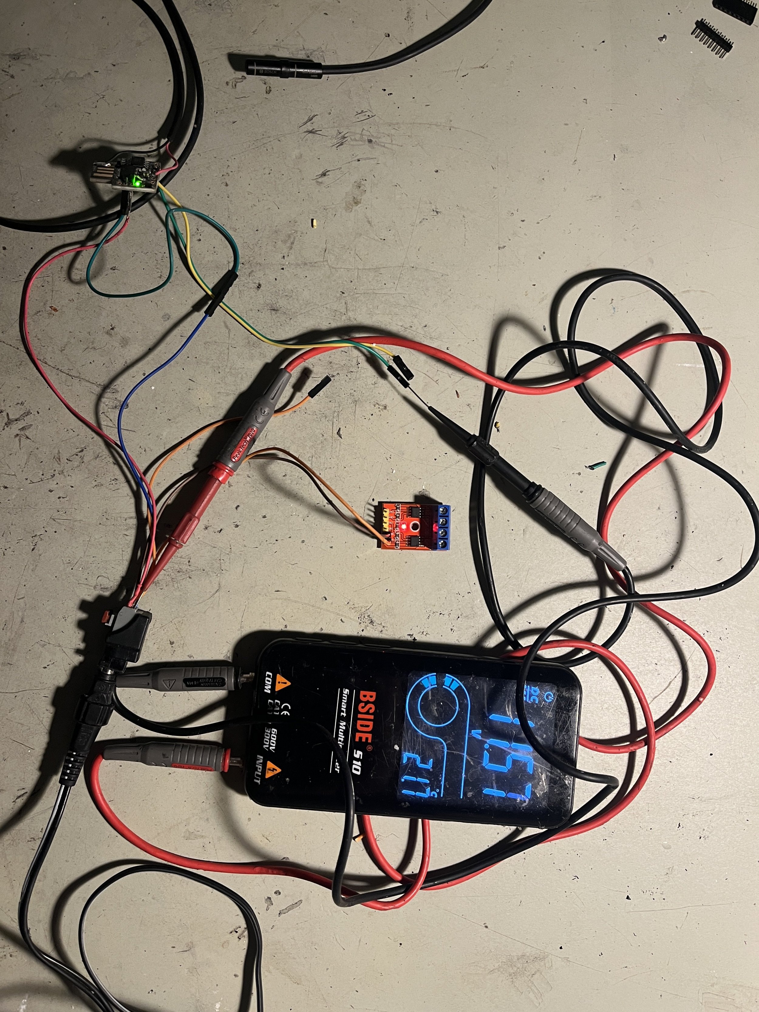
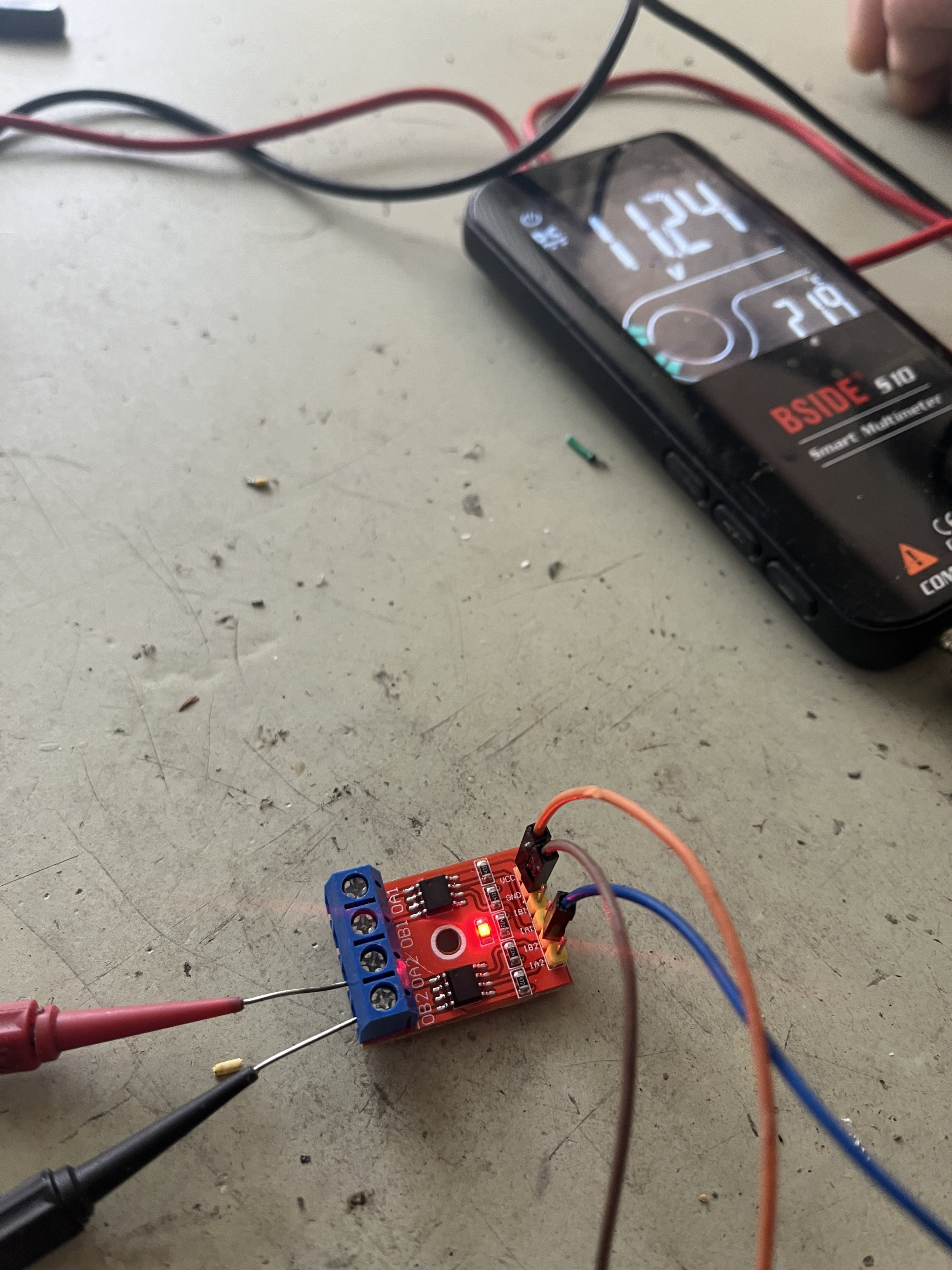
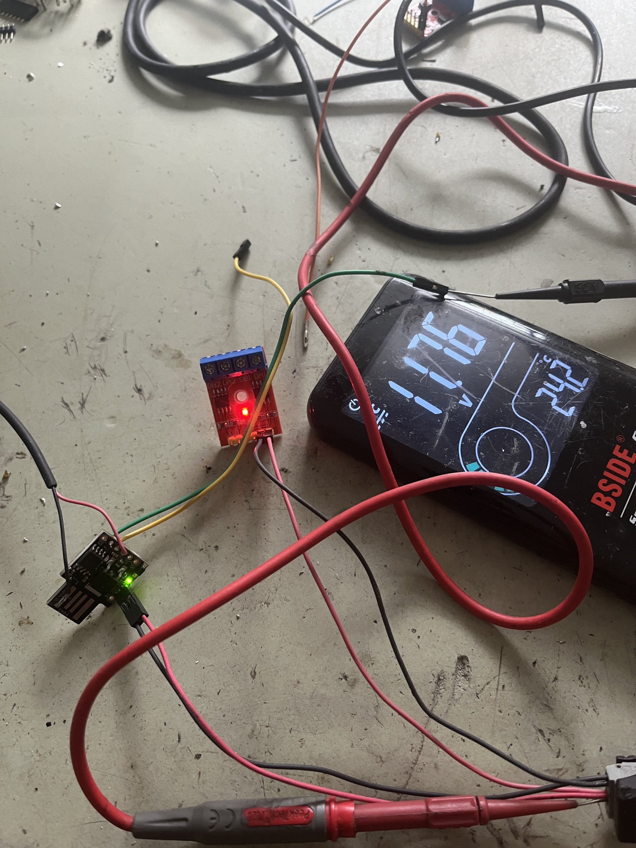
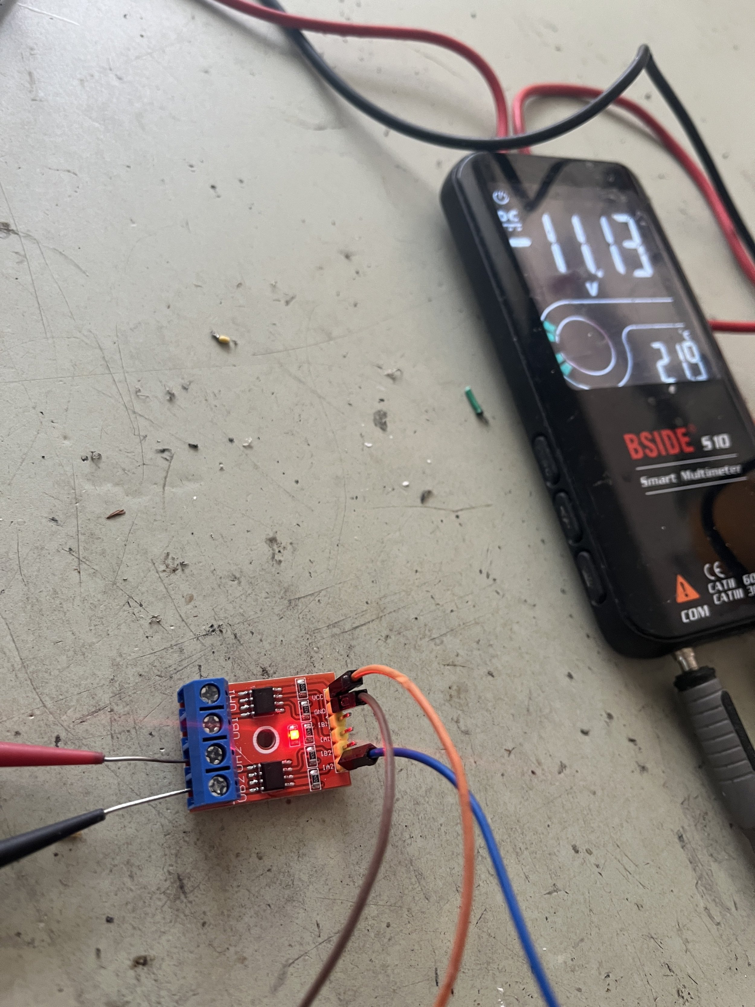
i tested the L9110 before without an arduino connected to it and could measure with my multimeter either +12v and GND on the motor out pins when i put on GND on A1A or -12v and GND if put gnd on A1B. So the h-bridge works as expected.
When i connect arduino and hbridge together AND DO ANYTHING ELSE after powering on this is the output of l9110:

Here you see voltages of the arduino pins 3/4 IMG_3744.jpeg


IMG_3743.jpeg
 
Last edited:

megabobra

Active member
Jul 24, 2022
266
268
Australia
Hey there,
when i tried the first time to test your code it didnt worked out but i wanted to check everything before proclaiming that and be sure that this wasnt caused by a wrong edited code. i dont need a variable multiplier but just a fixed value of 2.0 and i dont need a setup mode either so i deleted that part. To exclude these potential sources of errors i uploaded your code again with the changes you talked about:

#define REED_SENSOR_PIN 2
#define SETUP_PIN 6
#define ELECTROMAGNET_PIN 7
#define REDLED_LOWPRESSCOUNT_PIN 5
#define A1A 4
#define A1B 3


byte ButtonState;
byte LastButtonState;
byte Trigger = HIGH;
byte SetupState;

double LastPress = 0;
double CurrentPress = 0;
double EndMagnet = 0;
double MagnetDuration = 0;
double Delta;
double DeltaStatic;
double ActivateMagnetStart = 0;
double ActivateMagnetTemp = 0;
double MultiplierOut = 1;
double MagnetOnTime = 0;
double MultiplierCutOff = 1398; //1398 = 6kph/3.5mph

int Pressed = 0;
int PressCount = 0;
int MagnetSwitch = 0;
int MagnetOn = 0;


////////////////////
//change this MultiplierOut to alter max assistance speed. MultiplierOut 1.4 gives: 25kph * 1.4 = 35kph new max assitance
double MultiplierIn = 2.0;
double SetupDelay = 513;
double SetupWidth = 47;


void setup() {

pinMode(ELECTROMAGNET_PIN, OUTPUT);
pinMode(REED_SENSOR_PIN, INPUT_PULLUP);
pinMode(SETUP_PIN, INPUT_PULLUP);
pinMode(REDLED_LOWPRESSCOUNT_PIN, OUTPUT);
pinMode(A1A, OUTPUT);
pinMode(A1B, OUTPUT);
LastButtonState = digitalRead(REED_SENSOR_PIN);
SetupState = digitalRead(SETUP_PIN);
}

void loop() {

SetupState = digitalRead(SETUP_PIN);
//if we're in setup mode, run the consistent pulsing
if (SetupState == LOW) {
delay(SetupDelay);
//activate coil
digitalWrite(ELECTROMAGNET_PIN, HIGH);
digitalWrite(REDLED_LOWPRESSCOUNT_PIN, HIGH);
digitalWrite(A1A, HIGH);
digitalWrite(A1B, LOW);


delay(SetupWidth); //pulse width
//deactivate coil
digitalWrite(ELECTROMAGNET_PIN, LOW);
digitalWrite(REDLED_LOWPRESSCOUNT_PIN, LOW);
digitalWrite(A1A, LOW);
digitalWrite(A1B, LOW);
}
//outside of setup mode, function as normal
if (SetupState == HIGH) {
ButtonState = digitalRead(REED_SENSOR_PIN);

if ((ButtonState != LastButtonState) && (millis() - CurrentPress > 100)) {
//Button pressed
if (ButtonState == LOW) {
LastPress = CurrentPress;
CurrentPress = millis();
Delta = CurrentPress - LastPress;
Pressed = 2;
digitalWrite(REDLED_LOWPRESSCOUNT_PIN, HIGH);
if ((PressCount < 5) && ((CurrentPress - ActivateMagnetStart >= Delta) || PressCount > 0)) {

digitalWrite(ELECTROMAGNET_PIN, HIGH);
digitalWrite(A1A, HIGH);
digitalWrite(A1B, LOW);
Trigger = HIGH;
ActivateMagnetStart = CurrentPress;
MultiplierOut = MultiplierIn;
MagnetOnTime = millis();
MagnetOn = 1;

}
}
//Button released
if (ButtonState == HIGH) {
EndMagnet = millis();
MagnetDuration = EndMagnet - CurrentPress;
digitalWrite(REDLED_LOWPRESSCOUNT_PIN, LOW);
if (PressCount < 5) {
digitalWrite(ELECTROMAGNET_PIN, LOW);
digitalWrite(A1A, LOW);
digitalWrite(A1B, LOW);
MagnetOn = 0;
}
PressCount = PressCount + 1;
}
LastButtonState = ButtonState;
}
//if travelling slowly, fire coil 1:1
if (millis() - ActivateMagnetStart > MultiplierCutOff) {
PressCount = 0;
}

//If wheel stops on magnet after travelling slowly, turn off the coil after 2seconds
if ((MagnetOn == 1) && (millis() - MagnetOnTime > 2000)) {
digitalWrite(ELECTROMAGNET_PIN, LOW);
digitalWrite(REDLED_LOWPRESSCOUNT_PIN, LOW);
digitalWrite(A1A, LOW);
digitalWrite(A1B, LOW);
}

//Record one Delta to avoid continual changes to interval during multiplied interval below
if ((Trigger == HIGH) && (Delta > 0)) {
DeltaStatic = Delta;
Trigger = LOW;
}

//setup multiplier ramping
if (PressCount >= 5) {
if (PressCount < 10) {
MultiplierOut = (((MultiplierIn - 1) / 5) * (PressCount - 4)) + 1;
} else {
MultiplierOut = MultiplierIn;
}


if (millis() >= ActivateMagnetStart + DeltaStatic * MultiplierOut) {
if ((millis() < ActivateMagnetStart + DeltaStatic * MultiplierOut + MagnetDuration * MultiplierOut) && (Pressed > 0 )) {

//Magnet On
if (MagnetSwitch == 0) {
ActivateMagnetTemp = millis();
}
MagnetSwitch = 1;
digitalWrite(ELECTROMAGNET_PIN, HIGH);
digitalWrite(A1A, HIGH);
digitalWrite(A1B, LOW);
MagnetOnTime = millis();
MagnetOn = 1;

} else {

//Magnet Off
digitalWrite(ELECTROMAGNET_PIN, LOW);
digitalWrite(A1A, LOW);
digitalWrite(A1B, LOW);
ActivateMagnetStart = ActivateMagnetTemp;
Trigger = HIGH;
Pressed = Pressed - 1;
MagnetSwitch = 0;
MagnetOn = 0;
}
}
}
}
}

i tested the L9110 before without an arduino connected to it and could measure with my multimeter either +12v and GND on the motor out pins when i put on GND on A1A or -12v and GND if put gnd on A1B. So the h-bridge works as expected.
When i connect arduino and hbridge together AND DO ANYTHING ELSE after powering on this is the output of l9110:

Here you see voltages of the arduino pins 3/4 View attachment 141256


View attachment 141257

Let me post back later with a photo of the wiring from my spare bench setup so you can compare against your own. At best for now, all I have is a photo below of my current unit that's presently tucked away in the bike, but you can't see much of the L9110 in it!

Your connections should be:
Arduino 3 > L9110 motor A Input 1
Arduino 4 > L9110 motor A Input 2
Arduino Ground > L9110 Ground
Source 12v > L9110 positive input

Then you should be able to measure plus (or minus, depending on the motor's output direction) twelve volts across motor A outputs on the L9110. Just for fun, you can set the motor speed using: analogWrite(A1A, 255); where the A1A corresponds to whichever you selected as the HIGH output, and the speed ranges from 0 (stopped) to 255 (full speed). eg analogWrite(A1A, 127); should give you half speed, or 6v at the motor output.

Your code looks fine, though you mentioned you don't need setup mode yet setup mode is still in the code. Without knowing what the default state of that setup pin is with no connection, you might find you're entering setup mode anyway?


1716935681483.png
 

megabobra

Active member
Jul 24, 2022
266
268
Australia
Some additional photos of my test setup as promised:

1716970034811.png


connections to the L9110s:
1716969743686.png


Connections to the arduino to pins 7 and 8 per the code. Note that I'm simply using the 3.3v output in this case since this test unit is always powered by USB. In the unit in the bike, it's using the 5v output direct from the voltage regulator.
1716969768968.png
 

Peacepirate

New Member
May 22, 2024
8
0
Cologne
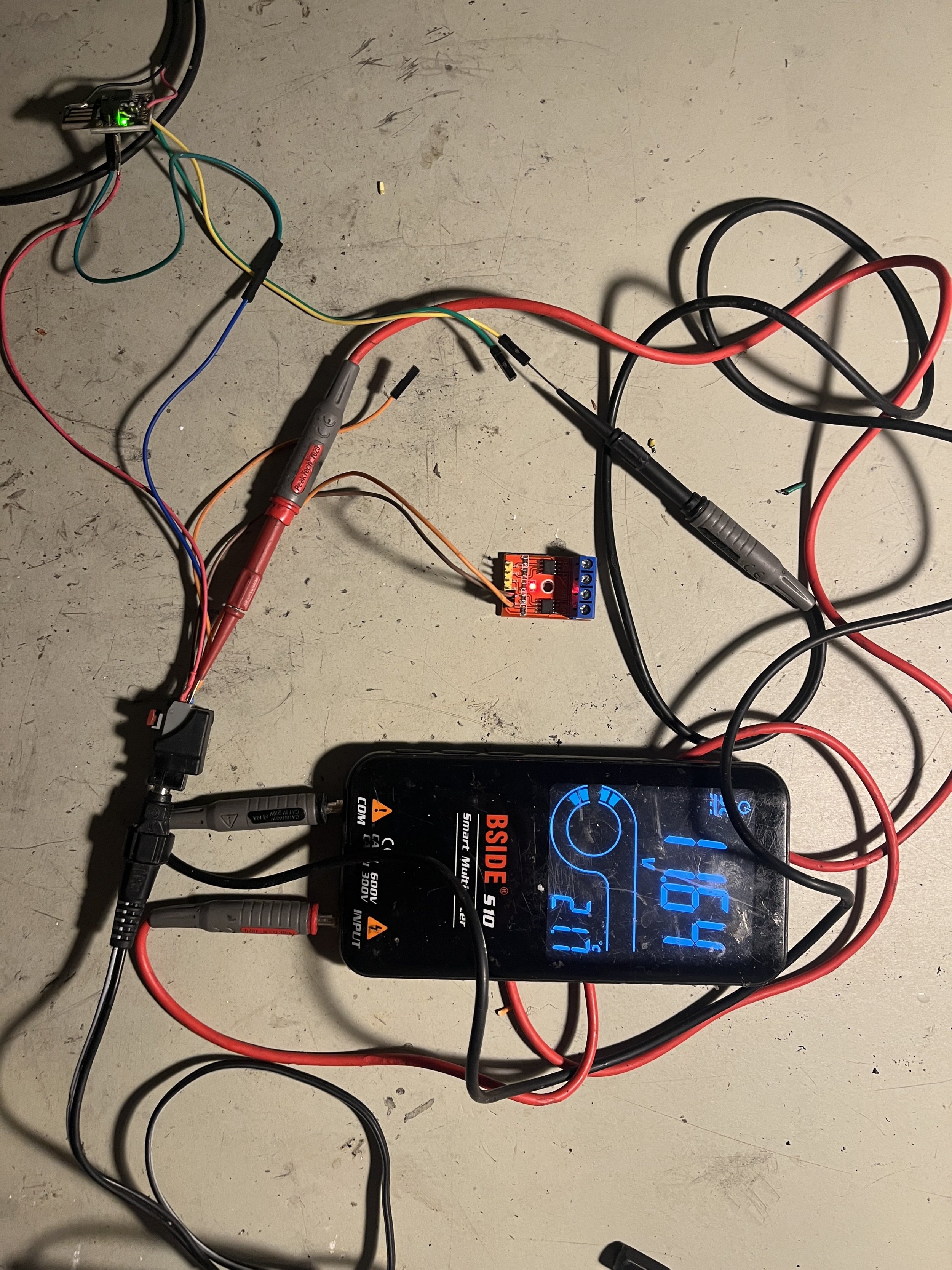
ok, once again. IMG_3746.jpeg IMG_3745.jpeg
Here we see that without arduino the voltage output of the h bridge switches between +12v and -12v - depending on whether gnd is on the left pin or the right pin. So if digispark switches to low (gnd) on pin 3 there should be 12v And if pin4 is on gnd there should be -12v.

We see in the video there is no stable voltage output but i varies. I believe that inside your setup mode you switch off/on automatically so its possible i am by default in this mode. How can i switch that mode off completly by code?
 

Peacepirate

New Member
May 22, 2024
8
0
Cologne
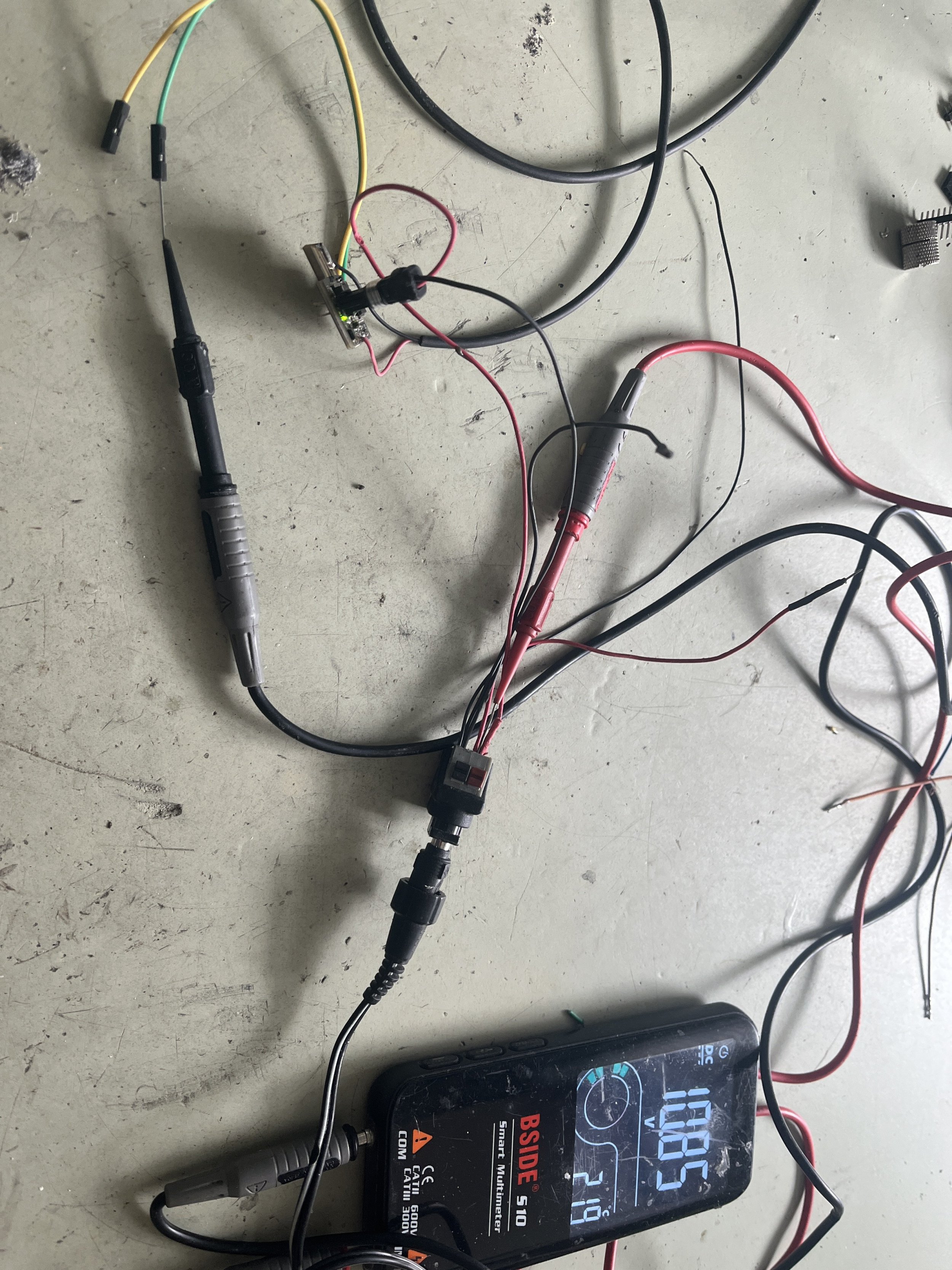
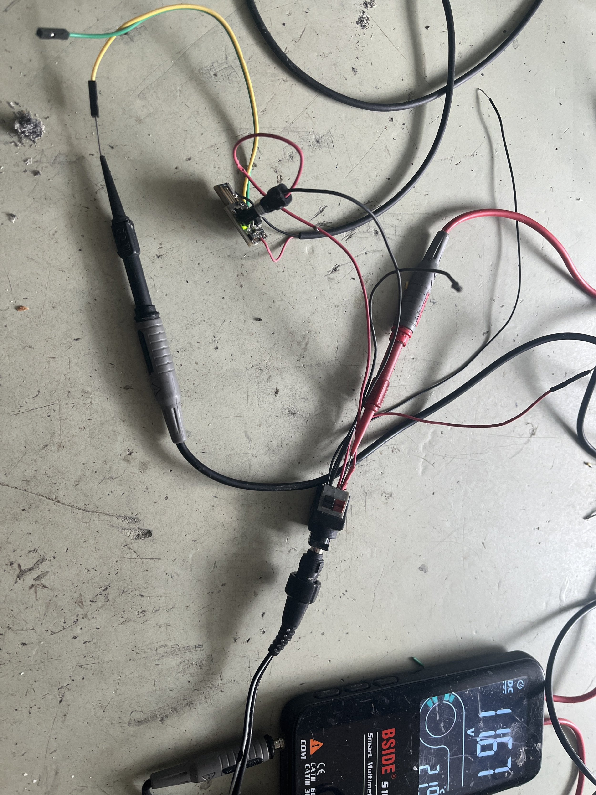
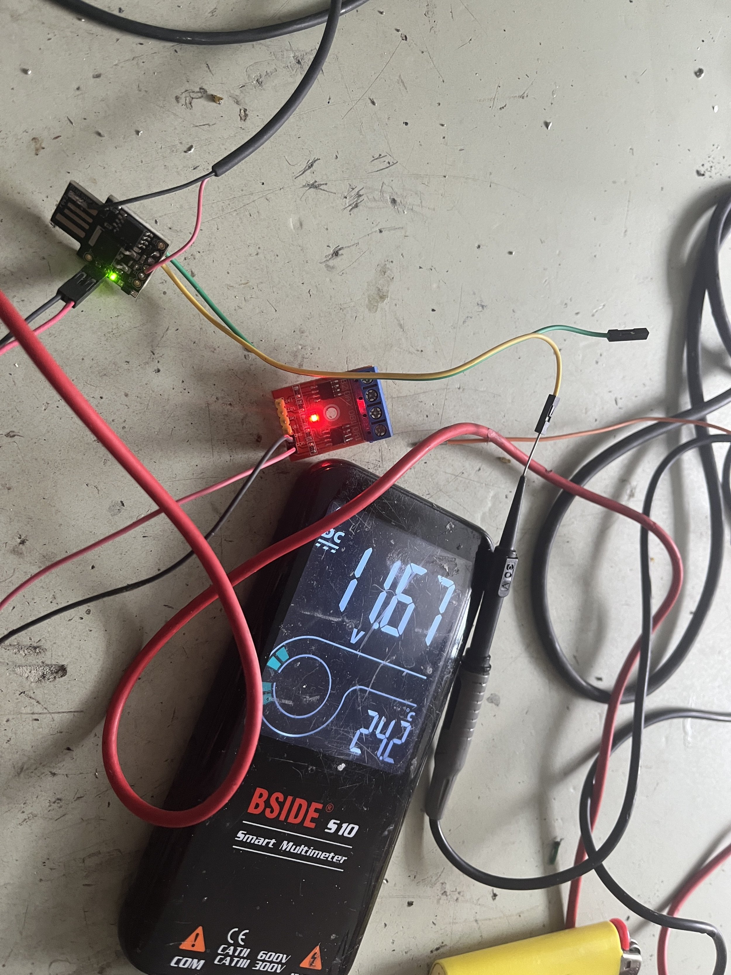
Now i am checking voltage on pin3 and 4.
digispark gets 12v
The red measuring tip of my Multimeter is on 12v directly and the black tip measures on pin4:
The voltage varies between 10,85v and 11,77 on pin4. .
When i measure pin3 (black tip in pin3 & red tip on 12v) i see constant and stable 11,67v.
I understand that if i see 11,67v on the multimeter the arduino has switched to low on pin3 and that means gnd is on pin3.

IMG_3748.jpeg IMG_3747.jpeg
 

Peacepirate

New Member
May 22, 2024
8
0
Cologne
I changed the code in line 56 from
SetupState = digitalRead(SETUP_PIN)
to
SetupState = HIGH
in order to deactivate setup mode. Hopefully i understood that correctly.

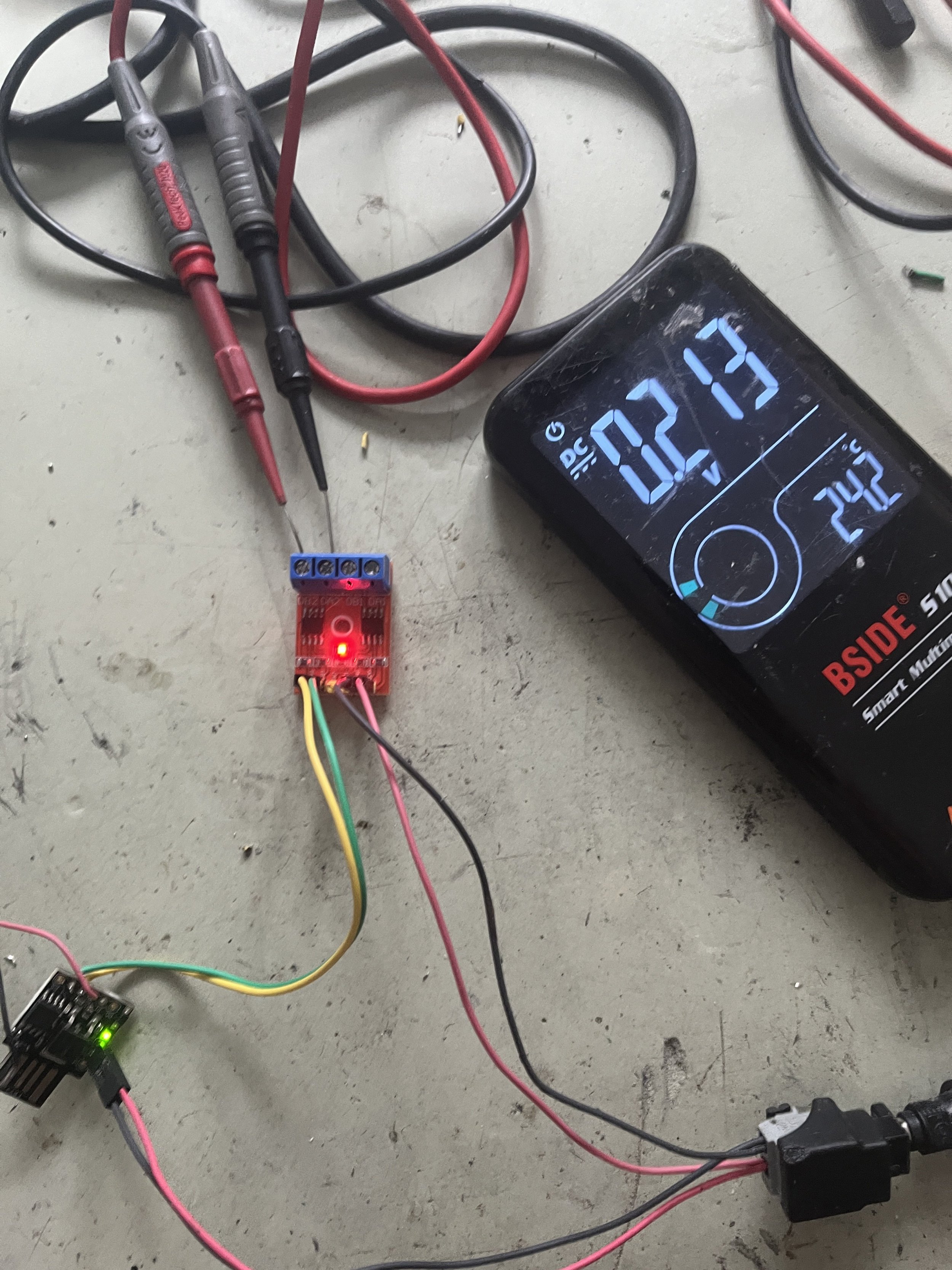
Now when i power on digispark and measure voltage on yellow / green (output_pins 3 /4) (red tip 12v / black tip pin3 or 4) i see quiete stable 11,67v on my multimeter.

IMG_3752.jpeg

IMG_3750.jpeg

This means Digispark switched both pins to LOW (GND).

When i connect both pins to L9110 h bridge i see very stable 0,215 voltage difference between motor output 1 and 2.
IMG_3753.jpeg

This seems to be more plausible because there shouldnt be any voltage changes on l9110 motor output if nothing has happened.
Now i am taking a magnet and use it to trigger the reed sensor once. Look at the video attached here.


All over sudden it seems as arduino starts to switch around those two pins permanently and i believe it should switch only once if it gets only one input signal shouldnt it? Instead this show is taking place. Goddamit…

I just checked what causes this behaviour after triggering reed sensor once and measured voltage on pin 3 and pin 4 in relation to 12v.
pin4 (green) is stable and doesnt change its gnd level (11,67v).
Yellow(pin3) is freaking around for some reason. Maybe i flash another digispark in case digispark is malfunctioning.
 
Last edited:

Peacepirate

New Member
May 22, 2024
8
0
Cologne
I took a new digispark and instead of the multimeter i connected an emagnet to the h bridge. I cannot distuinguish whether the small two pins are pulled and pushed away continously because the h bridge switches the polarity and thus creates a positive and a negative magnetic field but i believe this is the case. In contrast to your first build with only one magnetic pole i believe that the two pins are being really pushed away actively by the changing magnetic field. But the code is not working correctly at all because one input pin impuls results in endless output impulses and endless switching.
Here a link:
 

robbydobs

Member
Jan 31, 2021
102
92
Sussex, UK
I was thinking of giving this a go, but looking at the most recent comments, looks like it doesn't work, is that right? Does it cause an error?

I'm not sure if you've tried yet, but I was wondering if instead of a fixed multiplier you could instead simulate a lower gear ratio so that the cadence and wheel pulses match an feasible gear ratio (because I think Bosch builds up a histogram of likely gear ratios over time)
 

megabobra

Active member
Jul 24, 2022
266
268
Australia
I was thinking of giving this a go, but looking at the most recent comments, looks like it doesn't work, is that right? Does it cause an error?

I'm not sure if you've tried yet, but I was wondering if instead of a fixed multiplier you could instead simulate a lower gear ratio so that the cadence and wheel pulses match an feasible gear ratio (because I think Bosch builds up a histogram of likely gear ratios over time)

Howdy Robby,

Sadly it's not working on later/current Bosch motor firmware. Bosch seem to have tightened requirement of the magnetic field it's looking for meaning the simple electromagnet coil is no longer sufficient.

My unit is still running OK after ~1500km now but I'm back on firmware ~5 or so.


I do have a fix that I've been waiting to test but I'm not keen on updating my own motor in case it fails.

I'm keen to chat with anyone in Aus that has a smart system with up to date firmware and who is willing to have a go at a quick trial?
 
Last edited:

aegidius

Member
Sep 30, 2023
50
28
brisbane
I was wondering if instead of a fixed multiplier you could instead simulate a lower gear ratio so that the cadence and wheel pulses match an feasible gear ratio (because I think Bosch builds up a histogram of likely gear ratios over time)
Bosch have a patent on this method, so they either do it now or could do in the future.
I've tabulated the gear ratios in a spreadsheet and worked out good values for multipliers. The gear steps are not always exactly the same (since tooth counts are confined to integers) but they come out pretty close. Multipliers are either 1.18 or 1.39 (corresponding to one or two gear steps at the high end of the cassette). Seems to work for me but I'm not running too many kms on it to guard the warranty.
 

manu.w

Member
Aug 5, 2023
95
40
belgium
M
Bosch have a patent on this method, so they either do it now or could do in the future.
I've tabulated the gear ratios in a spreadsheet and worked out good values for multipliers. The gear steps are not always exactly the same (since tooth counts are confined to integers) but they come out pretty close. Multipliers are either 1.18 or 1.39 (corresponding to one or two gear steps at the high end of the cassette). Seems to work for me but I'm not running too many kms on it to guard the warranty.
My Son has an Bosch performance cx with a continuous Enviolo drive! So a min. max. and all in between 🤔
 

cplagz

New Member
Aug 24, 2024
2
0
Aus
I'm in Perth mate, have latest fw on rail 9 gen3 after eplus advanced sent me into error mode (auto speed on, 50kph limit, ~900kms)
I'd be happy to test yours out of you're still looking.... I still got two get out of jail free cards left
Howdy Robby,

Sadly it's not working on later/current Bosch motor firmware. Bosch seem to have tightened requirement of the magnetic field it's looking for meaning the simple electromagnet coil is no longer sufficient.

My unit is still running OK after ~1500km now but I'm back on firmware ~5 or so.


I do have a fix that I've been waiting to test but I'm not keen on updating my own motor in case it fails.

I'm keen to chat with anyone in Aus that has a smart system with up to date firmware and who is willing to have a go at a quick tria
 

megabobra

Active member
Jul 24, 2022
266
268
Australia
I'm in Perth mate, have latest fw on rail 9 gen3 after eplus advanced sent me into error mode (auto speed on, 50kph limit, ~900kms)
I'd be happy to test yours out of you're still looking.... I still got two get out of jail free cards left

Brilliant thanks. Is it a rim magnet setup though? Or Rotor magnet?
 

megabobra

Active member
Jul 24, 2022
266
268
Australia
Rotor magnet
Ahh ok gotcha. So the one I want to test is for is the rim magnet. For the rotor magnet, I'm pretty confident the existing megaboba tutorial will work - you should just position the electromagnet on the speed sensor rather than on the motor!
 

Arethustra

Active member
Subscriber
Apr 22, 2024
132
120
Bay Area, CA
For those of us with an attention deficit, is their an updated short version of where things are at with this? I’d love to get one if it will work with my Crestline (Rim Magnet/CX Race).
 

megabobra

Active member
Jul 24, 2022
266
268
Australia
For those of us with an attention deficit, is their an updated short version of where things are at with this? I’d love to get one if it will work with my Crestline (Rim Magnet/CX Race).

So if you're running rim magnet, the megabobra is confirmed working up to ~v5 on the motor firmware. After that point there hasn't been much luck.

If you're running rotor magnet, it should work regardless of firmware version.
 

EMTB Forums

Since 2018

The World's largest electric mountain bike community.

559K
Messages
28,287
Members
Join Our Community

Latest articles


Top