• Warning!!

    Riding a tuned or deristricted EMTB is not a trivial offence and can have serious legal consequences. Also, many manufacturers can detect the use of a tuning device or deristricting method and may decline a repair under warranty if it was modified from the intended original specification. Deristricting EMTB's can also add increased loads for motors and batteries. Riding above the local law limit may reclassify the bike as a low-powered bike, requiring insurance, registration and a number plate.

    Be aware of your local country laws. Many laws prohibit use of modified EMTB's. It is your responsibility to check local laws. Ignoring it, has potential implications to trail access, and risk of prosecution in the event of an accident.

    UK Pedelec Law

    Worldwide Laws

    We advise members great caution. EMTB Forums accepts no liability for any content or advice given here. 


MEGABOBRA: Bosch Smart System Derestriction for Rim Magnet - DIY Project with Support

manu.w

Member
Aug 5, 2023
100
46
belgium
My intended logic change I will make:
Thanks for the clarification, from the tests carried out the device behaves as you describe, but the problem of switching on the electromagnet for a complete wheel revolution remains, from the instrumental tests just carried out, the frequency in which what described happens is around 1Hz which corresponds to 8km/h considering a wheel circumference of 2300 mm. This it does every five revolutions at that specific frequency. I'm thinking it might be a defect in my seedling, later I'll try to change the output pin of the electromagnet. Until I see consistent behavior, I will not mount the device on the bike. I wouldn't want the Bosch anti-tuning software to generate an error when it sees a permanent signal for a wheel revolution while the pedals continue to rotate.
I will do further testing and keep you updated. Thank you and sorry for the comments.
See you soon, have a nice day.
This is a possible rider scenario, no? eg: downhill, constant wheel rotation, and pedaling (or not).
I think you all overestimate the implemented "error" detection of Bosch.
They can't impose us to pedal the way they want !?...
 

aegidius

Member
Sep 30, 2023
50
28
brisbane
Rotation of the pedals, with torque, cannot occur when the wheel appears stationary. The motor would throw a wheel sensor error, as it would think the sensor had failed.
 

manu.w

Member
Aug 5, 2023
100
46
belgium
Rotation of the pedals, with torque, cannot occur when the wheel appears stationary. The motor would throw a wheel sensor error, as it would think the sensor had failed.
Again , not always true imo
*very steep technical uphill, full power on pedals, speed almost zero
*doing a “stand still”

Really technical mtb need the power assist at low to zero speed. The way they capture the speed (wheel is turning) is really inaccurate…

If Bosch primary goal is to detect “derestriction” it will penalize the riding assistance experience .
And this is already the case, sad in my opinion.
 

aegidius

Member
Sep 30, 2023
50
28
brisbane
Agree. yes it is inaccurate at slow speeds, since they only measure once per revolution... but there will be a timeout value, if that is exceeded then you are trackstanding at best (and falling over at worst). They also (per their patent) can detect which gear you are in, so there will be an expected lowest wheel speed for any measured cadence.

I think they are not interested in detecting tampering at low speeds anyway. It's more to log sensor errors. But any derestricting "middle man" between sensor and motor needs to present as natural a set of wheel pulses as it can, so as not to arouse suspicion.
 

manu.w

Member
Aug 5, 2023
100
46
belgium
... They also (per their patent) can detect which gear you are in, so there will be an expected lowest wheel speed for any measured cadence.
...
Consider this:
For detecting the gear they need / have : wheel speed, pedal torque, pedal cadence , chainring and cassette gear ratio's as input i suppose. That last one i don't think it is stored somewhere?
The only accurate measured inputs are, pedal torque and pedal cadance, all the rest is innacurate or not realistic....
Do you have the formula for detecting the gear?
 
Last edited:

aegidius

Member
Sep 30, 2023
50
28
brisbane
There's a Bosch patent that talks about it. The motor samples cadence and wheel speed at regular intervals, divides one by the other to get a gear ratio, and forms a histogram of these gear ratios. Over time there should be sharp peaks corresponding to the physical ratios. If too many readings are off the peaks it throws an error. Presumably it would discard obvious bad data (wheel coasting, pedals being turned backwards, no torque, sensor sitting on magnet, etc)

Now the existence of a patent doesn't mean they are actually doing it, but it shows how they're thinking.
 

FRANK56

Member
Nov 5, 2023
14
7
Sardegna, Italia
I'm back with the updates. Unfortunately there is no good news for me. After finding a good position for the electromagnet with great difficulty, I took it for a test run. After less than 5 km I got the error 523003, "the speed sensor does not work correctly". I restarted the engine and for another 15km I enjoyed the engine until the new 523003. It also gave this error when positioning the coil, I had a lot of trouble finding a position where it didn't give the error for a period of 10 minutes. After the error 523003 comes out, you need to restart the system. But the biggest difficulty lies in a new feature probably included in this latest software version of the smart system, 9.13.0. After a certain amount of 523003 errors (about ten), the Hall sensor inside the motor is inhibited and no longer detects any speed. To restore operation you need to pedal with active assistance for about ten meters. This complicated things in the setup phase, as it was on my bike. to position the coil, you must remove the motor.
I will insist again, I think that in the new software version 9.13 they have refined the duty cycle control, in fact I think it is around 5%. As soon as I have some free time I get to work with a signal generator and do some tests with a very short duty cycle. My hardware is a Xiao RP2040 seeduino, hall sensor that reads a magnet on the disk, power taken from the controller on the main tube (13.3 V reduced to 5V with b.c), code megabobra150723.
Does anyone have experience with this latest software version? (9.13.0)
Greetings everyone.
 

manu.w

Member
Aug 5, 2023
100
46
belgium
I am on 8.16.0, reed switch and magnet on the spoke, running my own software that feeds the coil, only get now and then an error.

What do you mean with?:
I think that in the new software version 9.13 they have refined the duty cycle control, in fact I think it is around 5%.
 

FRANK56

Member
Nov 5, 2023
14
7
Sardegna, Italia
I am on 8.16.0, reed switch and magnet on the spoke, running my own software that feeds the coil, only get now and then an error.

What do you mean with?:
I think that in the new software version 9.13 they have refined the duty cycle control, in fact I think it is around 5%.
In detecting the wheel revolutions, the Bosch system, in addition to the frequency of passage of the magnet, also takes into account the duration of the on state created by the magnet as it passes. This has a duration that is expressed as a percentage of the entire rotation cycle of the wheel. In previous software versions this value was not decisive, with this latest version however it must fall precisely within certain parameters. This is what I think and it explains why 523003 errors easily occur. Mine is just a theory, but the facts lead me to think this.
 

manu.w

Member
Aug 5, 2023
100
46
belgium
In detecting the wheel revolutions, the Bosch system, in addition to the frequency of passage of the magnet, also takes into account the duration of the on state created by the magnet as it passes. This has a duration that is expressed as a percentage of the entire rotation cycle of the wheel. In previous software versions this value was not decisive, with this latest version however it must fall precisely within certain parameters. This is what I think and it explains why 523003 errors easily occur. Mine is just a theory, but the facts lead me to think this.
Hi,
Ok, yes, the duration ( energizing the magnet), is “obvious” if you want to mimic the rim magnet…”how long does the motor hall sensor sees the rim magnet” can be calculated depending on the wheel speed
 

aegidius

Member
Sep 30, 2023
50
28
brisbane
Feels reasonable to me that they would check the on-time of the sensor, it's very simple for them to do. They would need to ignore situations where the wheel just stops on the magnet by luck, but that's a zero to low speed situation.
 

AlumiPro

Active member
May 1, 2023
222
211
California
I'm back with the updates. Unfortunately there is no good news for me. After finding a good position for the electromagnet with great difficulty, I took it for a test run. After less than 5 km I got the error 523003, "the speed sensor does not work correctly". I restarted the engine and for another 15km I enjoyed the engine until the new 523003. It also gave this error when positioning the coil, I had a lot of trouble finding a position where it didn't give the error for a period of 10 minutes. After the error 523003 comes out, you need to restart the system. But the biggest difficulty lies in a new feature probably included in this latest software version of the smart system, 9.13.0. After a certain amount of 523003 errors (about ten), the Hall sensor inside the motor is inhibited and no longer detects any speed. To restore operation you need to pedal with active assistance for about ten meters. This complicated things in the setup phase, as it was on my bike. to position the coil, you must remove the motor.
I will insist again, I think that in the new software version 9.13 they have refined the duty cycle control, in fact I think it is around 5%. As soon as I have some free time I get to work with a signal generator and do some tests with a very short duty cycle. My hardware is a Xiao RP2040 seeduino, hall sensor that reads a magnet on the disk, power taken from the controller on the main tube (13.3 V reduced to 5V with b.c), code megabobra150723.
Does anyone have experience with this latest software version? (9.13.0)
Greetings everyone.
You’re encountering what I did. (Previous posts) I’ve disconnected my Megabobra because I was frustrated riding with speratic 523003 and 523001 error codes. My Megabobra has the reed, not hall sensor.
I have pre ordered the new Speedbox 1.2B designed for the Bosch Rim Mag system. I asked them if it will work with the most recent Bosch firmware updates. They responded; “Yes, it will be tested on the latest software updates.”
I’ll post how this system performs🤞🏻
Scheduled to ship out around the end of this month.
My firmware is currently 8.16.0
I would be happy with a derestriction device that can be turned on and off using the Bosch mini wireless remote, or….? To reduce error codes, because I don’t need over 20mph all the time, and when I do need it, I know ahead of time and would engage the device via bar mounted button.
 

FRANK56

Member
Nov 5, 2023
14
7
Sardegna, Italia
You’re encountering what I did. (Previous posts) I’ve disconnected my Megabobra because I was frustrated riding with speratic 523003 and 523001 error codes. My Megabobra has the reed, not hall sensor.
I have pre ordered the new Speedbox 1.2B designed for the Bosch Rim Mag system. I asked them if it will work with the most recent Bosch firmware updates. They responded; “Yes, it will be tested on the latest software updates.”
I’ll post how this system performs🤞🏻
Scheduled to ship out around the end of this month.
My firmware is currently 8.16.0
I would be happy with a derestriction device that can be turned on and off using the Bosch mini wireless remote, or….? To reduce error codes, because I don’t need over 20mph all the time, and when I do need it, I know ahead of time and would engage the device via bar mounted button.
Hello, it will be very interesting to know how the speedbox device works. I read your posts about your megabobra device. I believe your problems, like mine, are largely due to the construction of the electromagnet coil. @manu.w has the same software version as you but doesn't have these problems. It should be noted that he uses his own code and not the megabobra code. I have a new software version, 9.13.0. I will continue the tests, if anyone would like to suggest solutions for the coil it would be a great courtesy to me. I currently have a coil with about 200 turns of 0,15 mm wire for a resistance of 13.5 ohm, placed directly on the motor casing and I power it at 5 volts.
 
Last edited:

manu.w

Member
Aug 5, 2023
100
46
belgium
Hi Alumipro,
If you are brave and curious, you could open the electromagnet case and see and measure the resistance of the coil. I made different coils , some didn’t worked …
Maybe share, if they allow that, the installation instructions .
Let us know how this sb works
Thanks
Any news on your bought ?
 

manu.w

Member
Aug 5, 2023
100
46
belgium
Hello, it will be very interesting to know how the speedbox device works. I read your posts about your megabobra device. I believe your problems, like mine, are largely due to the construction of the electromagnet coil. @manu.w has the same software version as you but doesn't have these problems. It should be noted that he uses his own code and not the megabobra code. I have a new software version, 9.13.0. I will continue the tests, if anyone would like to suggest solutions for the coil it would be a great courtesy to me. I currently have a coil with about 200 turns of 0,15 mm wire for a resistance of 13.5 ohm, placed directly on the motor casing and I power it at 5 volts.
My e-magnet:
7.8ohm @12V = 1.5A
1704925164940.png
 

FINJP

New Member
Sep 30, 2023
5
1
Middle of Finland
Hi, Just thinking a difference like Cube vs. bike on the previous tube video.
In the Cube motor is more straightly aligned, but that one is more like upright,
and distance with rim-magnet is more far than like Cube. So field must not be so sensitive, right? (same firmware with engine, or are they different depending the brand or design)
Sensor is located on the board close to guys middle finger if i am right.
 

megabobra

Active member
Jul 24, 2022
271
272
Australia
Hi guys,

I've been running my updated setup with hall sensor and new coil since early December and it's working well. Changes from the original design in the tutorial are as follows:
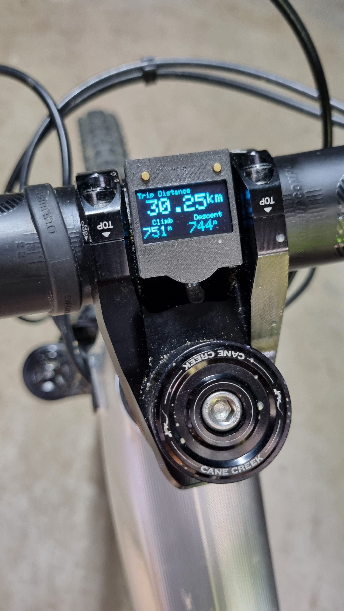
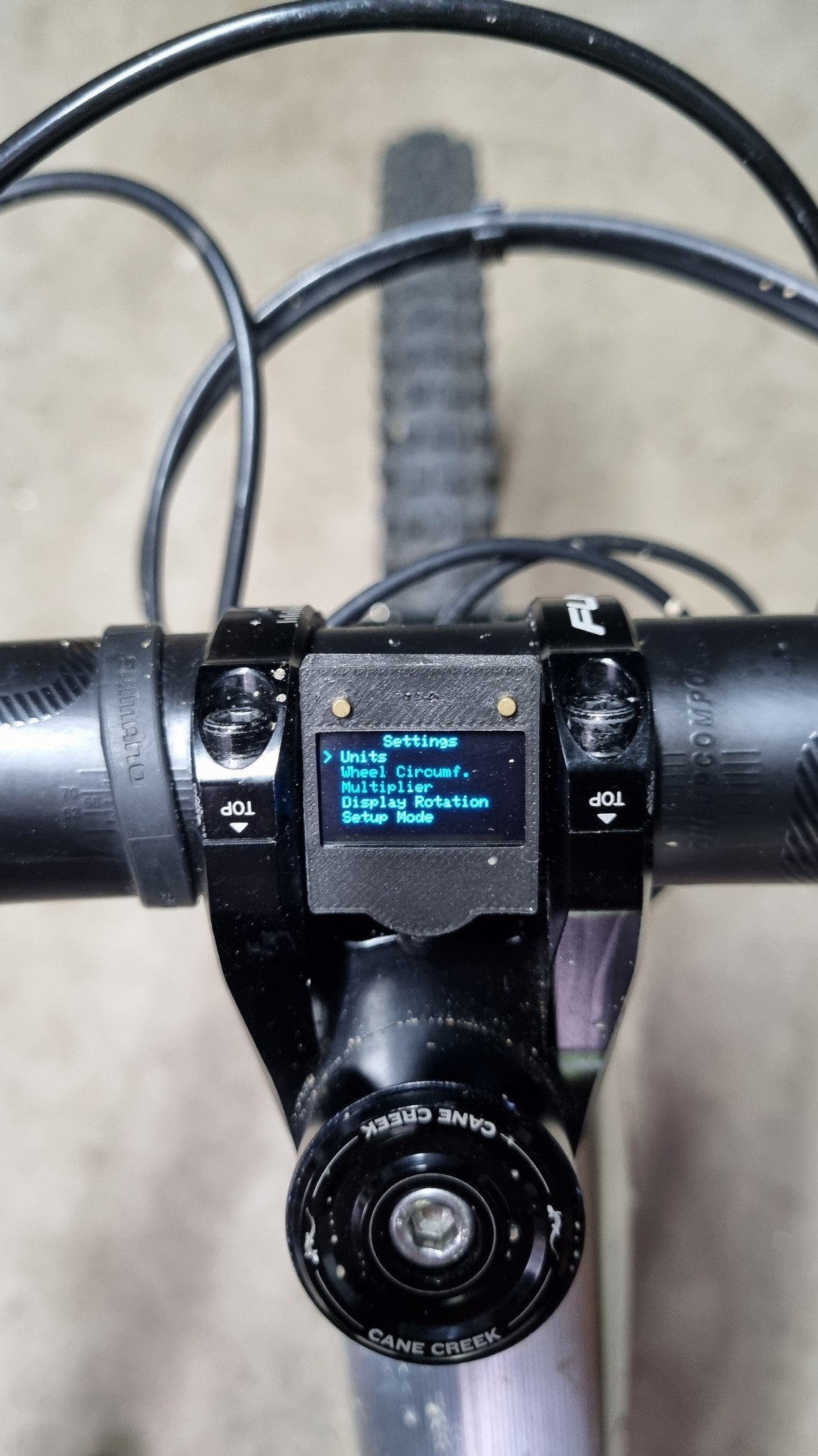
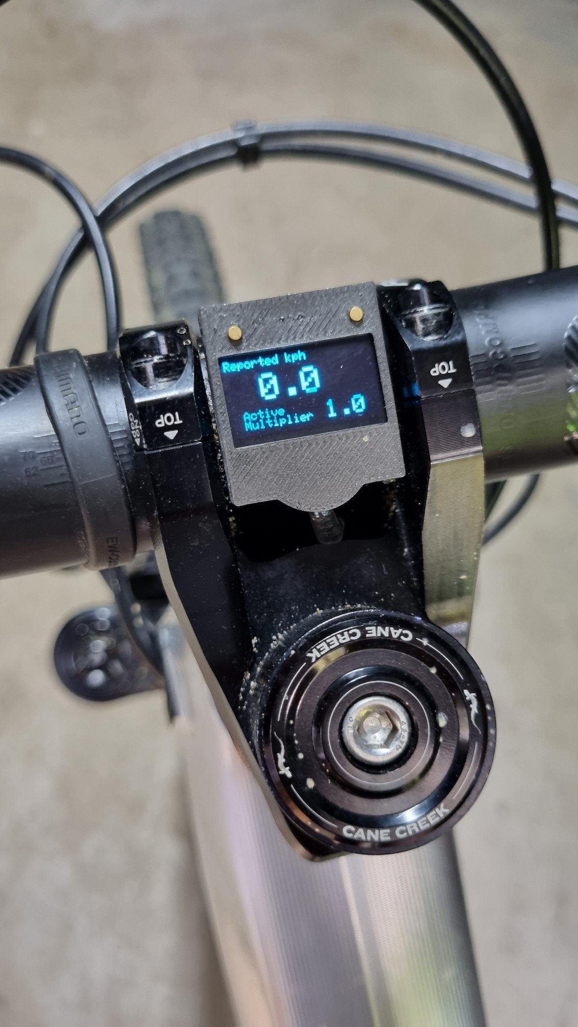
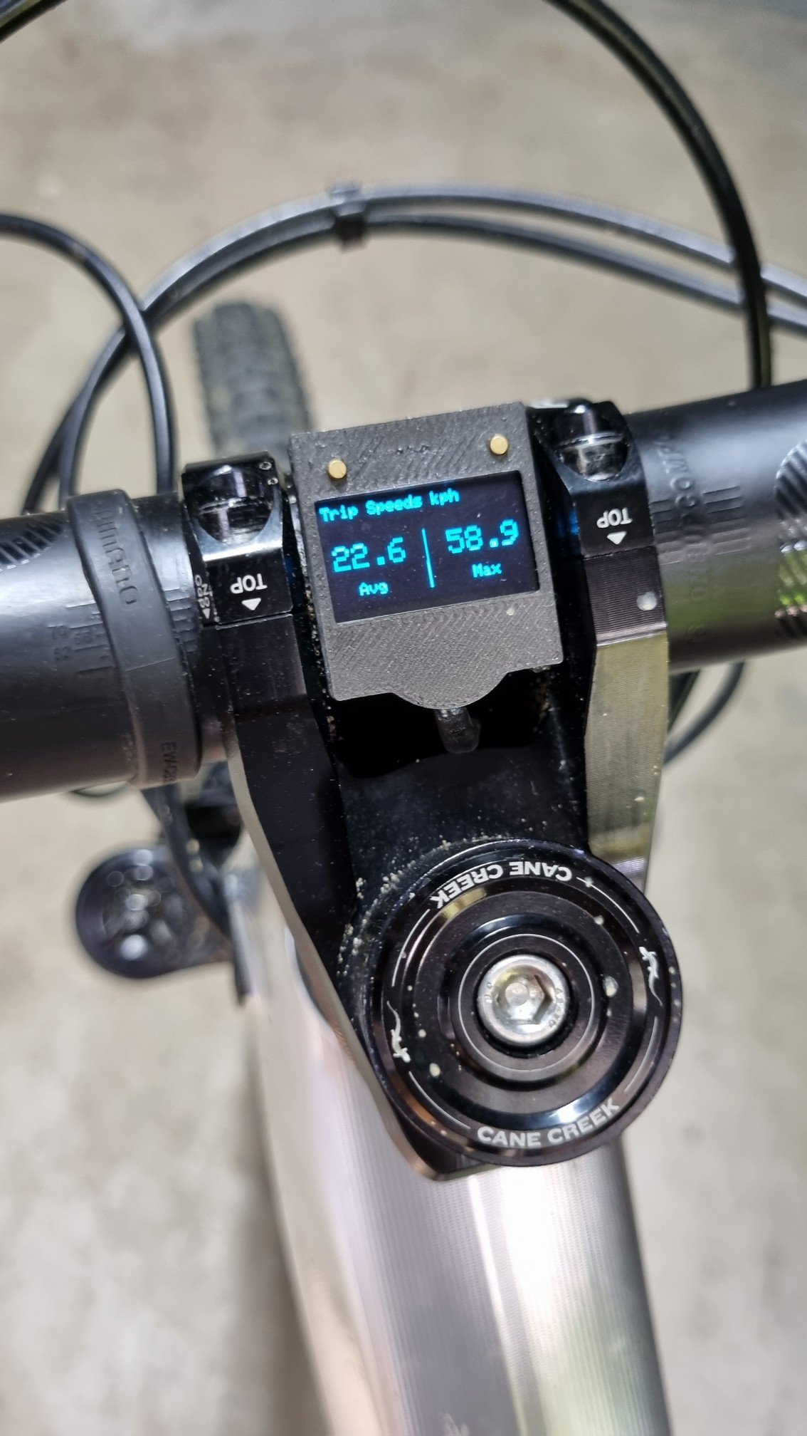
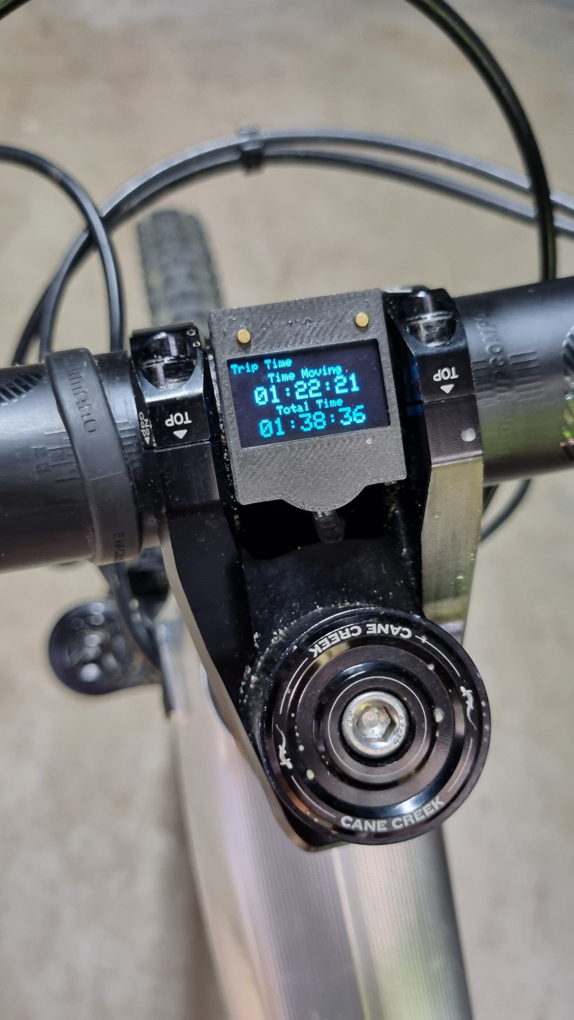
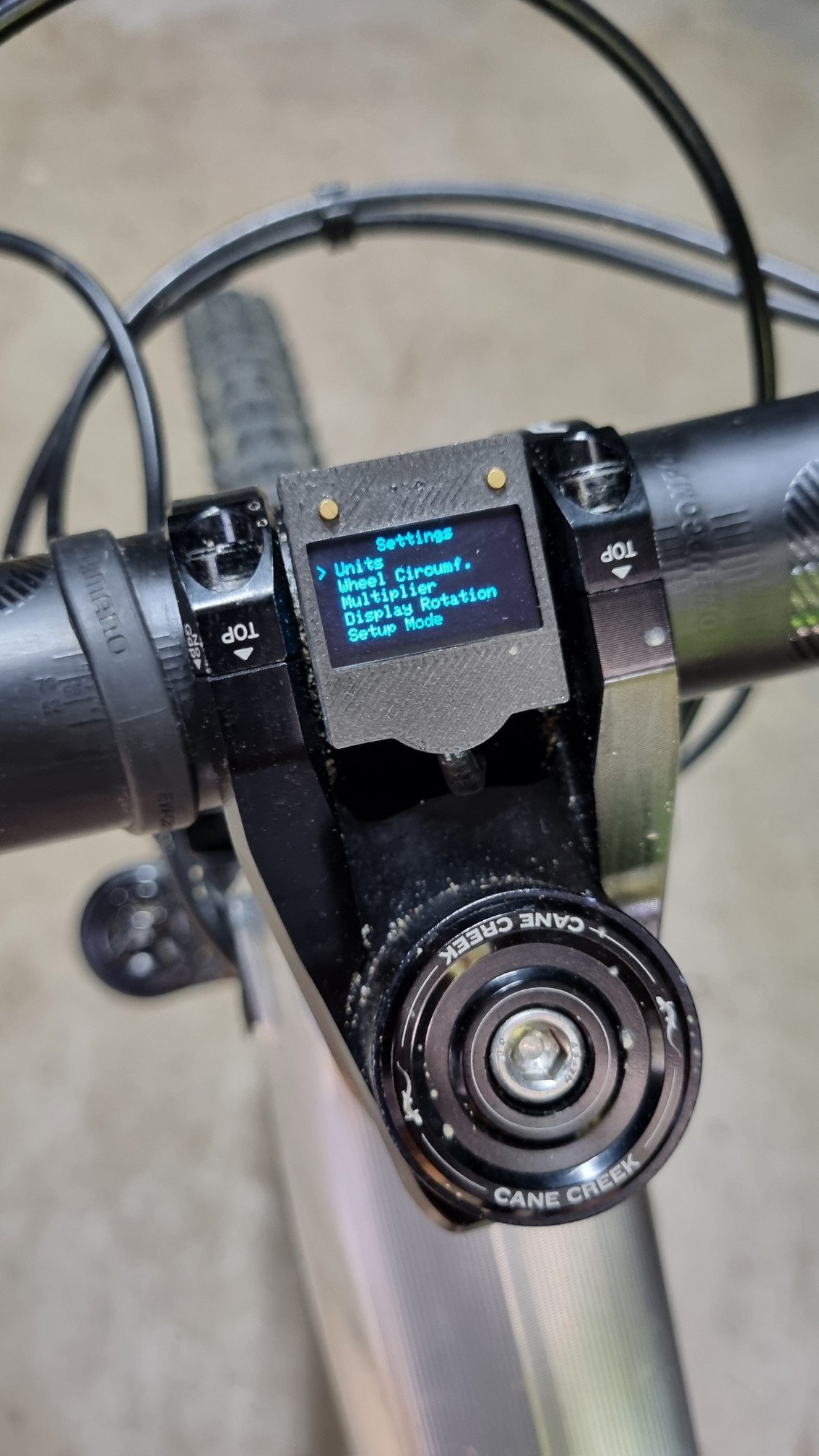
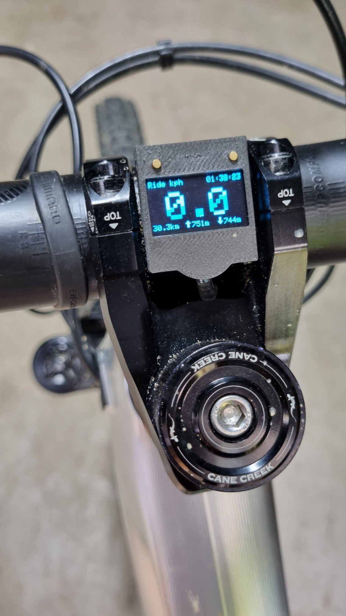
  • Addition of small OLED display with two buttons to show simple ride stats and allow for user configuration of the device
  • Addition of barometer to capture elevation/climb without the risk of introducing GPS to the Bosch controller
  • Switched to Hall sensor, replacing reed switch, at the wheel - solves issues around vibration and is less sensitive to placement
  • New miniature electromagnet coil
  • Several code tweaks
    • Updated multiplier behaviour. When multiplier is being introduced (or removed), it's done so relative to speed rather than wheel rotations. This allows the multiplier to be run at a partial level (say, 1.2 when your programmed figure is 1.5) when traveling slowly. Multiplier now is stepped back down when slowing, rather than simply switching off immediately. This corrects the speed fluctuations some were seeing when slowing down before coming to a stop.
    • Enhanced Setup Mode, which can now be activated via the display controls, which gives live feedback on hall sensor strength to assist wtih optimum sensor placement at the wheel.
I experimented with a magnetometer to capture the passing of the rim magnet from within the motor area. This actually works fine, with my current code allowing the user to switch between use of Hall sensor or magnetometer for magnet pickup. However, the challenge is running a strong enough magnet on the rim to overcome environmental noise (the magnetometer is just a digital compass after all, sensitive enough to be affected by Earth's magnetic field), but not so strong that the motor itself picks it up. Bosch have it easy because they just use a super strong magnet on the rim to easily overcome the noise. But the window between the noise and the Bosch pickup is just too small to be reliable. Apart from the loss of a wire to the wheel, I don't really see an advantage of this method over the Hall sensor, so that's what I've been using.

As for the new electromagnet coil, it measures ~8mm high with a footprint of 10mm. It's in a 3D printed case with flat bottom so attaches easily to the motor and is lower than the motor 'seam' (that joins the two halves) so will never have interference with the bike frame. Given its smaller size and uniform shape, placement is easier BUT it's not foolproof. For the coil itself, I've moved from 4.2v to 5v, reduced wire diameter to 0.1mm and now machine-wind around a small steel cylinder. This gives the magnetic field more focus rather than acting on the coil alone. After intial placement, I still had to move the coil once (even after a clear result in Setup Mode) but it's been solid since.


I had been planning on withholding the code/details from this update as it didn't sit well with me that the commercial players are selling the original setup for big dollars. But a post this morning from a buyer of the Speedbox 1.2b Rim Magnet showing a maniuplation error made me laugh. Even with the code handed to them they still managed to get a detection error that no one using the megabobra code ever saw!!

Anyway, I'm going to update the original tutorial to include the small change for the Hall sensor, as well as instructions for the optional stuff around the display and barometer, and of course with the new code to accompany it. The extra components add complexity and can be a bit fiddly to put together, but if anyone's up for the challenge, please do give it a go. There's certainly room for improvement: there's no waterproofing around the screen!

Finally, some photos attached of the display. It's mounted in between the arms of my stem so it's fairly tucked away. Visibility is fine in all but direct sunlight.

Image00002.jpg Image00003.jpg Image00001.jpg Image00006.jpg Image00005.jpg Image00004.jpg Image00007.jpg
 

FRANK56

Member
Nov 5, 2023
14
7
Sardegna, Italia
Hi Megabobra, happy to read you again. Congratulations on the evolution of your work. However, I want to ask you which software version you are testing your project on. I currently have 9.13.0 and after several attempts to use your project with seeeduino with only the hall sensor variant instead of the reed, I have suspended the attempts for the moment. Error 523003 haunted me. I suspect that Bosch, in its latest version 9.13.0, has started using the detection of at least two axes on the internal hall sensor. In fact, after the error comes out, even when restarting the bike, the internal hall sensor of the motor no longer detects the pulses of the electromagnet. To solve the problem, you need to replace the original magneto and make several turns of the wheel to restore the magneto reading. If this were the case, we should think about providing at least a bipolar magnetic signal. To do this I'm making a coil with a double winding, so that I can also generate a negative pulse via another Arduino pin. However, I continue to follow your work with great interest, have a nice day.
 

megabobra

Active member
Jul 24, 2022
271
272
Australia
Hi Megabobra, happy to read you again. Congratulations on the evolution of your work. However, I want to ask you which software version you are testing your project on. I currently have 9.13.0 and after several attempts to use your project with seeeduino with only the hall sensor variant instead of the reed, I have suspended the attempts for the moment. Error 523003 haunted me. I suspect that Bosch, in its latest version 9.13.0, has started using the detection of at least two axes on the internal hall sensor. In fact, after the error comes out, even when restarting the bike, the internal hall sensor of the motor no longer detects the pulses of the electromagnet. To solve the problem, you need to replace the original magneto and make several turns of the wheel to restore the magneto reading. If this were the case, we should think about providing at least a bipolar magnetic signal. To do this I'm making a coil with a double winding, so that I can also generate a negative pulse via another Arduino pin. However, I continue to follow your work with great interest, have a nice day.

Hi Frank,
Let me check the version tomorrow to confirm, I'm not sure off-hand, but it must be an older one as I'm not facing those problems.

I actually picked up some L9110S stepper motor drivers to accommodate a reversing pulse but had the need to get it setup. You might find using something like this simpler than a second winding as you can retain all the same connections and just send a 'reverse' command to the L9110S, reversing the current flow and thus the magnetic field.
 

FRANK56

Member
Nov 5, 2023
14
7
Sardegna, Italia
Hi Frank,
Let me check the version tomorrow to confirm, I'm not sure off-hand, but it must be an older one as I'm not facing those problems.

I actually picked up some L9110S stepper motor drivers to accommodate a reversing pulse but had the need to get it setup. You might find using something like this simpler than a second winding as you can retain all the same connections and just send a 'reverse' command to the L9110S, reversing the current flow and thus the magnetic field.
The use of the L9110S is an excellent idea, I await your news on the firmware version and possibly also the specifications of your new mini electromagnet.
 

manu.w

Member
Aug 5, 2023
100
46
belgium
@megabobra
Is your current setup using the + and - pulse generation?

On my setup I only use a + pulse on drive unit ver. 8.16.0
I now and then get the error, after +40km continuous riding, not systematic… to resolve it I restart and I am good to go.
 

megabobra

Active member
Jul 24, 2022
271
272
Australia
@megabobra
Is your current setup using the + and - pulse generation?

On my setup I only use a + pulse on drive unit ver. 8.16.0
I now and then get the error, after +40km continuous riding, not systematic… to resolve it I restart and I am good to go.

No not at the moment. I got the driver in case I encountered trouble but didn't need it. I might give one a go on my bench setup to in case I'm actually a long way behind on the firmware...
 

aegidius

Member
Sep 30, 2023
50
28
brisbane
There is also the possibility that the new SW is looking at the values of its measured gear ratio (which changes with multiplier) and seeing that they are not fitting into a previously gathered histogram of gear ratios, as per that Bosch patent I've been banging on about. Might be a red herring but you never know.
 

megabobra

Active member
Jul 24, 2022
271
272
Australia
There is also the possibility that the new SW is looking at the values of its measured gear ratio (which changes with multiplier) and seeing that they are not fitting into a previously gathered histogram of gear ratios, as per that Bosch patent I've been banging on about. Might be a red herring but you never know.

Anything's possible of course but I'm still a bit skeptical of this. I just think there's too many variables that are unaccounted for. And sure, Bosch want to demonstrate that they're policing the max speed rule for a given market, but surely not at the expense of false positives being thrown.

EG with the histogram, if I'm 110kg and sell my bike to someone who weighs 70kg, the relationship between cadence and speed across that histogram is going to be very different. This method also wouldn't catch events of a derestriction on a brand new bike as there's no history to compare to.

If there's something new, my money is on the + - pulse.
 

aegidius

Member
Sep 30, 2023
50
28
brisbane
EG with the histogram, if I'm 110kg and sell my bike to someone who weighs 70kg, the relationship between cadence and speed across that histogram is going to be very different.
I doubt that this is true - regardless of how fast or slow you pedal the relationship between cadence and speed will fall into a fixed set of gear ratios (assuming the wheel circumference and cogs do not change). The patent talks about measuring the sharpness of the peaks and looking for readings that fall outside the peaks, as would happen if a multiplier were varying smoothly.

But I'm probably being paranoid here - companies often patent stuff they later end up not using. In any event, in my version I'm using multipliers that correspond closely to the ratios between two existing gears, just to be safe. I don't have enough data to say if this makes a difference, and probably will never know for sure.
 

megabobra

Active member
Jul 24, 2022
271
272
Australia
I doubt that this is true - regardless of how fast or slow you pedal the relationship between cadence and speed will fall into a fixed set of gear ratios (assuming the wheel circumference and cogs do not change). The patent talks about measuring the sharpness of the peaks and looking for readings that fall outside the peaks, as would happen if a multiplier were varying smoothly.

But I'm probably being paranoid here - companies often patent stuff they later end up not using. In any event, in my version I'm using multipliers that correspond closely to the ratios between two existing gears, just to be safe. I don't have enough data to say if this makes a difference, and probably will never know for sure.

You're right, I guess my example is more around torque than gear ratios!
 

megabobra

Active member
Jul 24, 2022
271
272
Australia
@megabobra
Is your current setup using the + and - pulse generation?

On my setup I only use a + pulse on drive unit ver. 8.16.0
I now and then get the error, after +40km continuous riding, not systematic… to resolve it I restart and I am good to go.

Eeep I'm on Software version 5.17.0 on the drive unit! App version 1.17.2(1037).

I'll spend some time to integrate the + - pulse behaviour on my test bed. I'll come back with an update.

I don't think I'm brave enough to update the drive unit firmware though!!
 

EMTB Forums

Since 2018

The World's largest electric mountain bike community.

563K
Messages
28,513
Members
Join Our Community

Latest articles


Top