• Warning!!

    Riding a tuned or deristricted EMTB is not a trivial offence and can have serious legal consequences. Also, many manufacturers can detect the use of a tuning device or deristricting method and may decline a repair under warranty if it was modified from the intended original specification. Deristricting EMTB's can also add increased loads for motors and batteries. Riding above the local law limit may reclassify the bike as a low-powered bike, requiring insurance, registration and a number plate.

    Be aware of your local country laws. Many laws prohibit use of modified EMTB's. It is your responsibility to check local laws. Ignoring it, has potential implications to trail access, and risk of prosecution in the event of an accident.

    UK Pedelec Law

    Worldwide Laws

    We advise members great caution. EMTB Forums accepts no liability for any content or advice given here. 


Derestricting bosch smart system

Sander

Member
Dec 29, 2022
56
29
NL
Hi Sander,

I used 0.25mm wire for magnet I wound. If you're on 5v and approx that diameter, you shouldn't need a resistor. Just add a few more turns if you find your resistance isn't there. But in this case, close enough is good enough, as you can always adjust the placement of the coil a little as well!
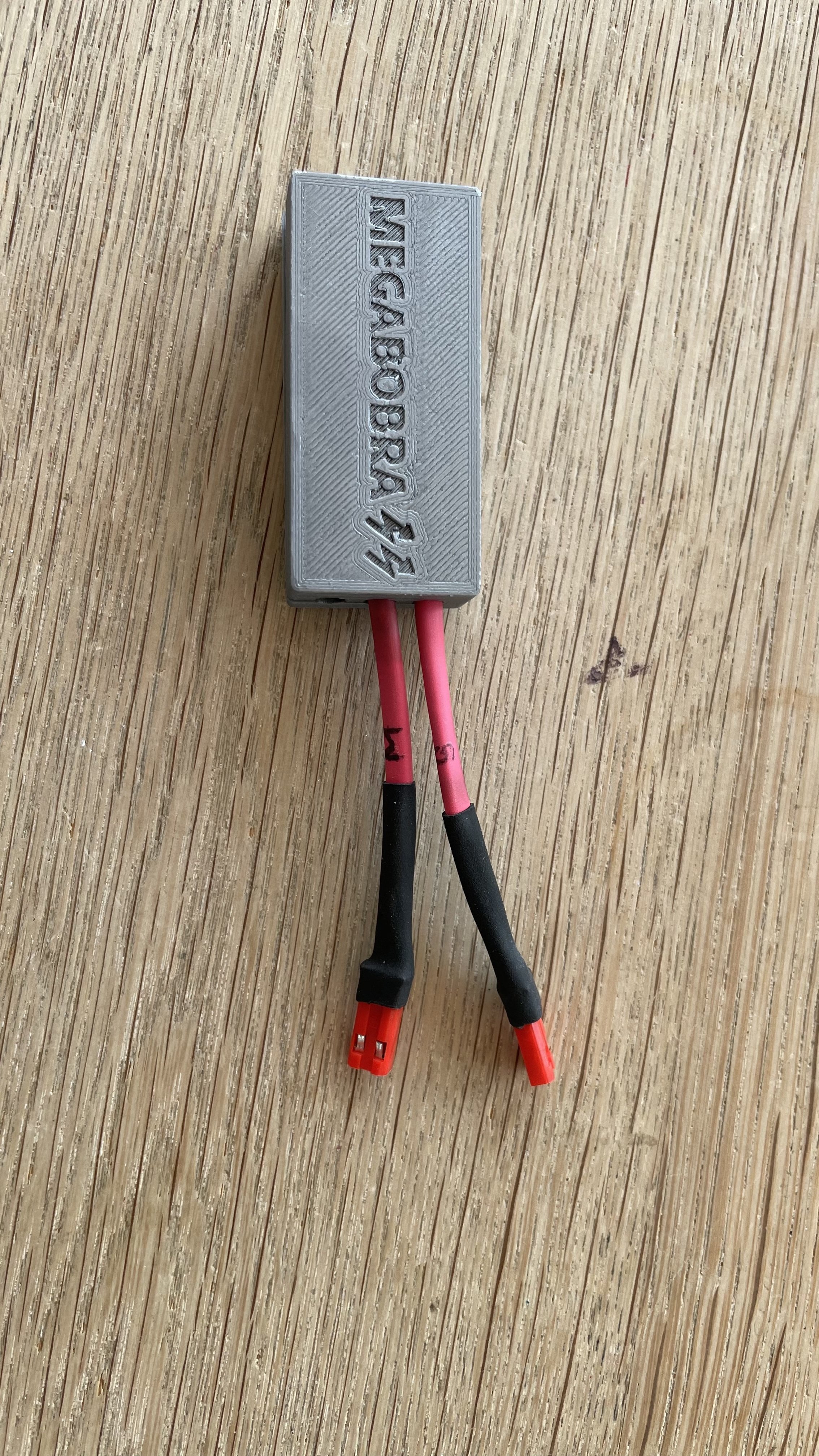
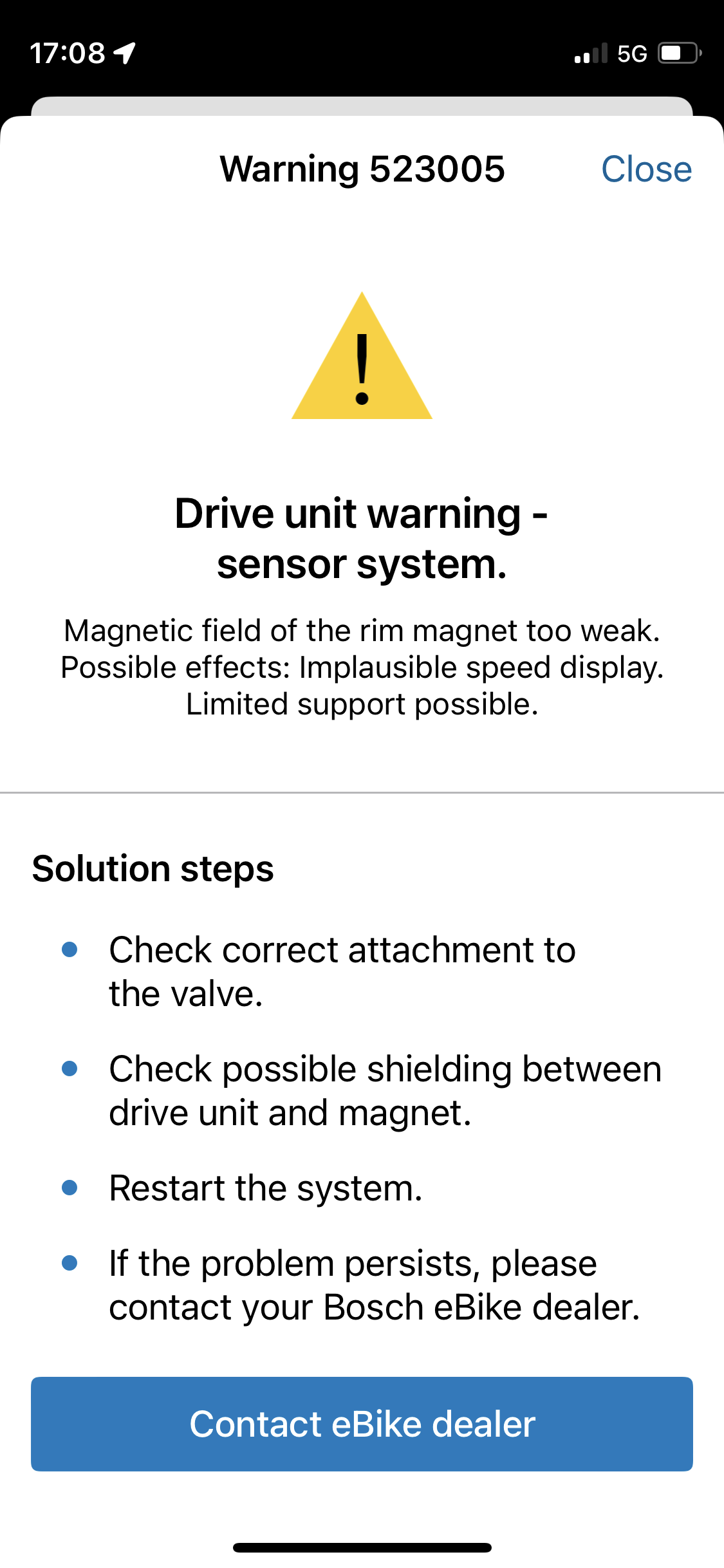
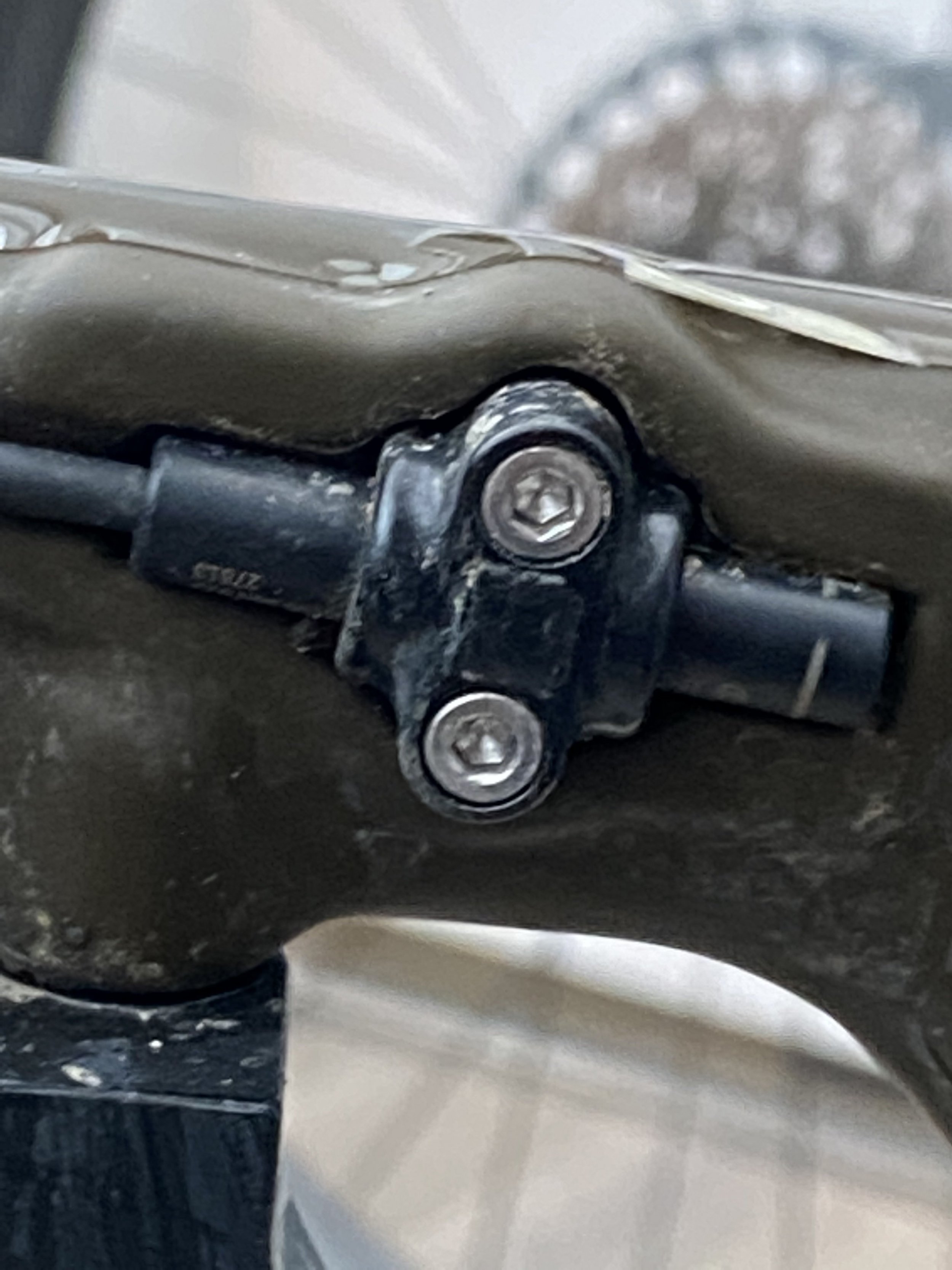
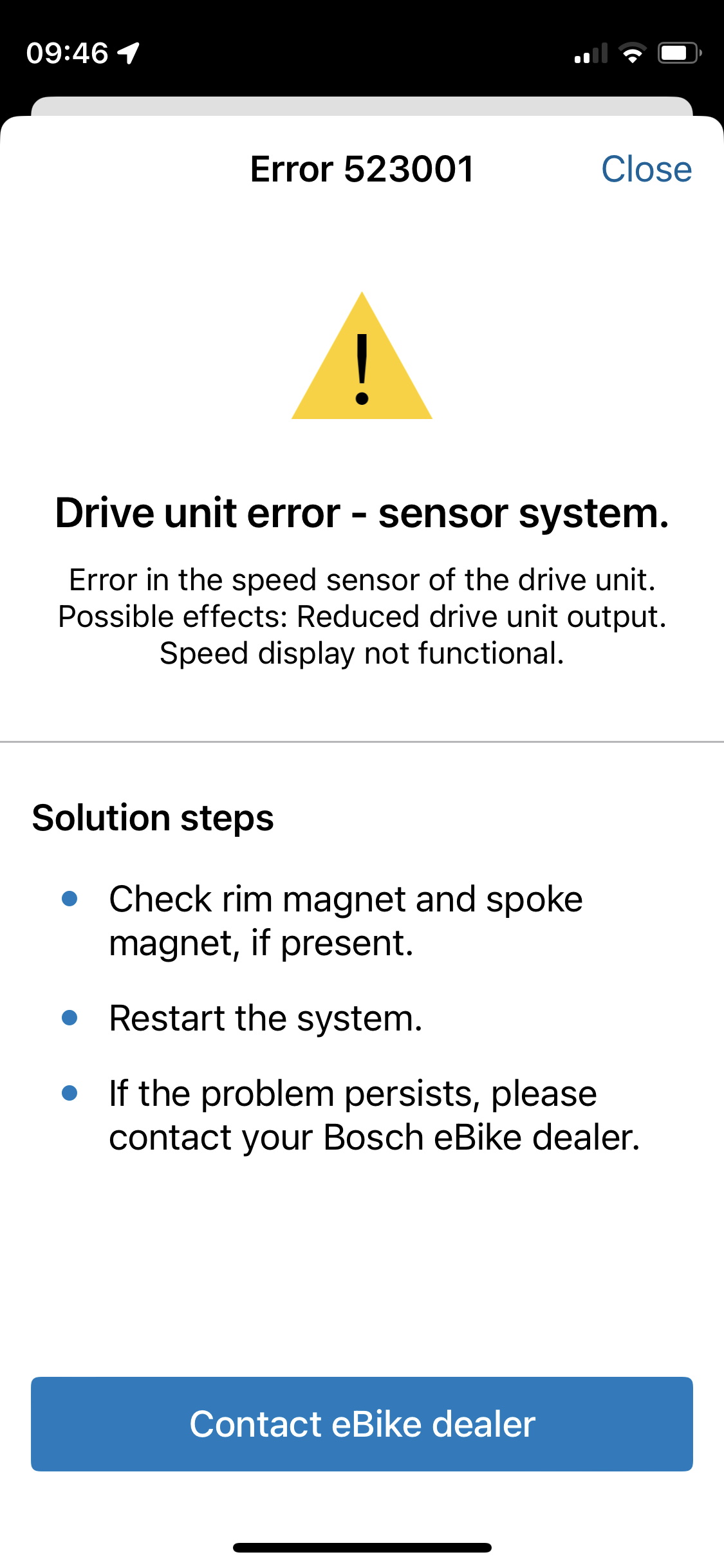
First of all: it works nicely :) Sunday I rode 40km on my local trail. I had 1 hic-up, but I think the electromagnet shaked to much. In my app I'm getting an error 523005 "weak signal", but the motor still works great. This morning I rotated the electromagnet towards the motor. Because of lack space I have to place the magnet on top of the motor instead of at the back of the motor. So turning it should give a stronger field and no weak error anymore? Turns out that the motor stopped working and gave me an error 523001. So I turned the magnet outward again and no problems anymore (except the error). This weekend I'm gonna make the magnet coil myself and place it in the back of the motor. See what happens. To be continued.

closed.jpg IMG_2584.PNG IMG_2583.PNG
 

megabobra

Active member
Jul 24, 2022
269
271
Australia
First of all: it works nicely :) Sunday I rode 40km on my local trail. I had 1 hic-up, but I think the electromagnet shaked to much. In my app I'm getting an error 523005 "weak signal", but the motor still works great. This morning I rotated the electromagnet towards the motor. Because of lack space I have to place the magnet on top of the motor instead of at the back of the motor. So turning it should give a stronger field and no weak error anymore? Turns out that the motor stopped working and gave me an error 523001. So I turned the magnet outward again and no problems anymore (except the error). This weekend I'm gonna make the magnet coil myself and place it in the back of the motor. See what happens. To be continued.

View attachment 106712 View attachment 106713 View attachment 106714

Great news Sander. Yes I got those same errors when setting up. Luckily they're just diagnostic errors rather than anything serious, restarting the system should clear it.

The placement of the magnet is what does it. Just keep moving it around until it clears up. Or as you're going to, try your own winding for more flexibility. Once you find the right spot it should be clear. I've got ~220km on mine now and haven't seen those messages since the initial couple of rides.

Ps, love the printed case ;)
 

stratosa

Member
Apr 17, 2020
42
14
GREECE
Hi Sander,

I used 0.25mm wire for magnet I wound. If you're on 5v and approx that diameter, you shouldn't need a resistor. Just add a few more turns if you find your resistance isn't there. But in this case, close enough is good enough, as you can always adjust the placement of the coil a little as well!
First i would like to say that i admire you, magabobra that you started this and sander for continuing. I have an idea of using a magnet at the front wheel like garmin uses, then via bluetooth, signal is tranmitted to an electromagnet attached externally to the motor, powered by the auxillary,(like you did) which fires half the times. Does it make any sense?
 
Last edited:

megabobra

Active member
Jul 24, 2022
269
271
Australia
First i would like to say that i admire you, magabobra that you started this and sander for continuing. I have an idea of using a magnet at the front wheel like garmin uses, then via bluetooth, signal is tranmitted to an electromagnet attached externally to the motor, powered by the auxillary,(like you did) which fires half the times. Does it make any sense?
Thanks Stratosa. Bluetooth would add some complexity but certainly possible. Just remember you'll need some sort of controller, like the Arduino, to run the bluetooth receiver and the electromagnet at the motor end.
 

megabobra

Active member
Jul 24, 2022
269
271
Australia
Apologies for the repost of some of this, but this single post can be a single point of reference for the rim magnet derestrict.

My build is based on an Ardunio microcontroller, reed switch and electromagnet. I removed the bike's rim magnet and instead placed a traditional magnet on the disc rotor. The Arduino then uses the reed switch to sense the true RPM of the wheel, delays the time between magnet passes by a fixed multiplier and then activates the electromagnet at the new interval accordingly. The electromagnet is positioned up against the motor case.

With ~100 lines of code, everything is working great. I've got the multiplier set to 1.4 (eg where true speed is 20kph, motor will be shown 20/1.4= 14.3kph), giving a new max assisted speed of 35kph. The multiplier could be set to anything, say 2 would give assist to 50kph.

The beauty of this setup is the simplicity: no interruption of sensors from the motor, reducing chance of detection. So long as you don't go crazy with the multiplier, it'd be very difficult for the motor to detect this manipulation, as there are so many real-world variables which will mask it; rider weight, gear ratio, terrain etc. Some things may give it away though. For example, if you use a large multiplier, you may reach a point where for a given cadence it's just not physically possible to be traveling so slowly. Also if you use location tracking through the Eplus app, it may compare wheel speed with GPS speed and flag a discrepancy.

Some FAQ:

  • YES it will disrupt your total trip distance and odometer, but it's a simple multiplication to get the true figures. ie reported trip distance * chosen multiplier = true trip distance.
  • YES it should work on setups without the rim sensor. Instead of positioning the elctromagnet against the motor case, position it against the speed sensor.
  • Total power usage when the magnet is firing is ~2.4watts, and negligable when it's not firing (ie when the bike is stationary). Magnet is firing only around 8% of the time.


Here's a quick tutorial so you can build your own derestrictor for the smart system with rim magnet.

Components:
Of course there's plenty of equivalent components you can substitute here, so go with what's cheap/easy to get locally.


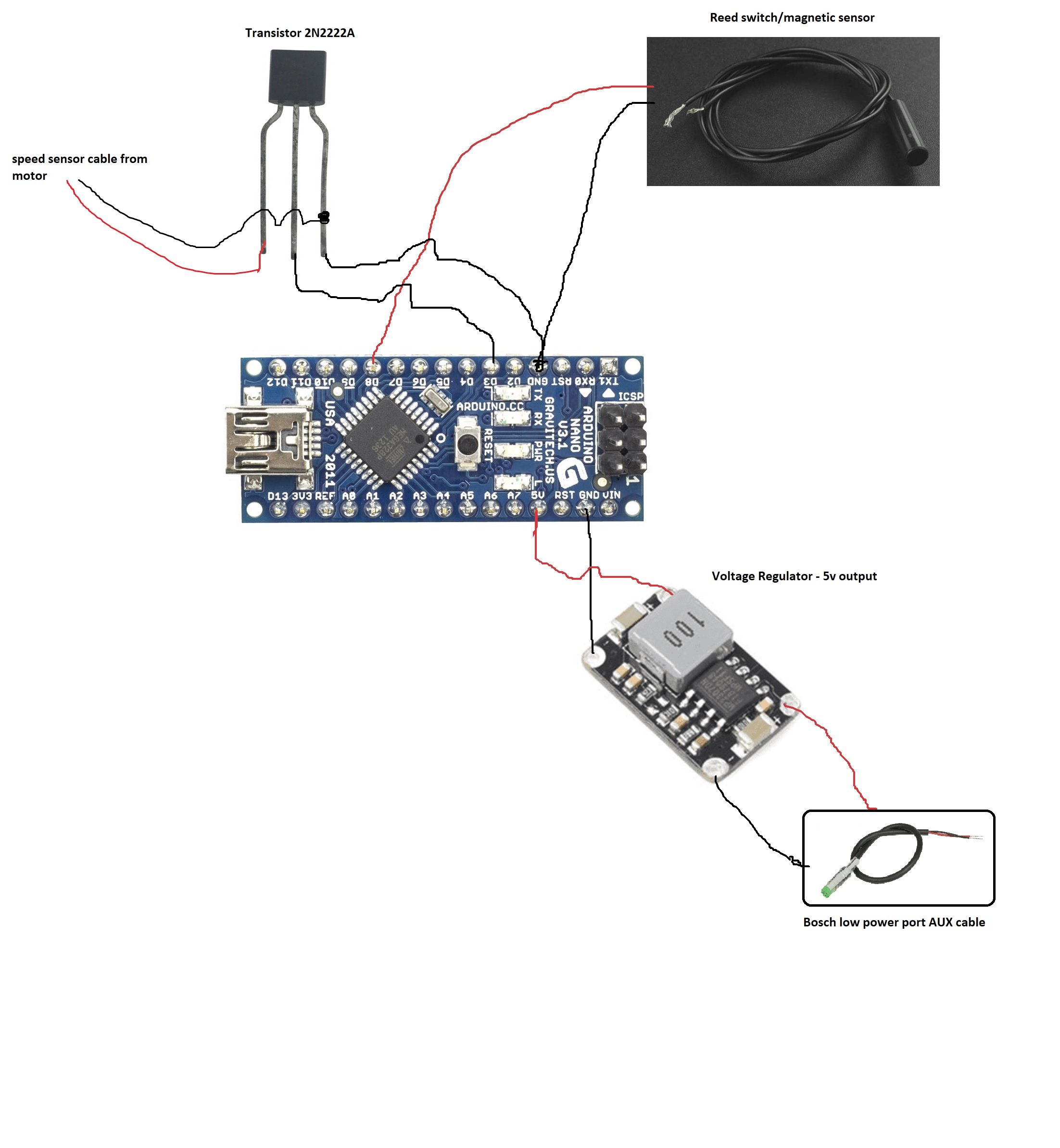
Wiring Schematic:

Reed switch: D8 and Ground
Transistor: Base > Ground, emitter > electromagnet, collector > D3
Electromagnet: 5v and transistor's collector leg
Voltage regulator: 5v and Ground

View attachment 105957

The Arduino nano has a built in regulator, so you can also wire the ~13v from the Bosch low power port direct to the Vin and Ground pins in order to omit the voltage regulator above. I had a spare regulator so figured I'd use it to monitor temperatures.

Note that you'll need your Bosch dealer to enable to the low power port before it will be powered.

I was also able to build my own electromagnet with some enameled copper wire. You need a coil resistance of ~15ohms. I used 100 turns around some pvc pipe ~ 25mm in diameter and a 0.5watt 10ohm resistor.

View attachment 105975

These work just as well as the commercial electromagnet and offer better flexibility of placement. If i was starting from scratch, it'd use this rather than the off the shelf product.


Programming

Load the attached code to the Arduino Nano with Arduino IDE. You can download it here.

You can update the Multiplier variable in the code (line 26) to alter the maximum assistance speed. I've got mine set to 1.4. This slows the actual wheel rpm by a factor of 1.4, moving the maximum assistance speed from 25kph to 35kph.


Installation

Snap the magnet on to the rear disc rotor. Mount the magnetic switch on the swing arm so that it's close to the rotating magnet.
The placement of the electromagnet is a bit tricky as the motor measures the strength of the magnet field, not just if a field exists. I found it best to mount the magnet facing AWAY from the motor (ie magnetic face towards the rear of the bike). Refer to the pics attached for my placement location. I'm using some foam to wedge it in place.

Once wired, the Arduino Nano and all wiring gets pushed into the frame.


Good luck and let me know if there are any questions. View attachment 105963 View attachment 105964 View attachment 105965 View attachment 105976 View attachment 105977

Hi all,

I've made a change to the code above, and updated the tutorial's code file accordingly. New version attached here too.

I found that big multipliers didn't behave well around fast accelerations from stopped, or while traveling very slowly; up a technical climb for example.
I've made a change now to restore the actual wheel magnet interval (ie multiplier = 1) when traveling < 6kph (or mph equiv). This ensures quicker speed reporting to the motor in those stop-start motions.
When speed increases above 6kph, the multiplier is introduced gradually over five wheel revolutions, to make sure there isn't a weird step backwards in reported speed when the multiplier kicks on. After these five revolutions, the full multiplier is applied as before.

How much this change impacts your ability to retain actual distance (reported distance * chosen multiplier = actual distance) depends on how much time you spend traveling at <6kph - so I'd say not much!
 

Attachments

  • Rampup Code 210323.txt
    2.8 KB · Views: 204
Last edited:

Sander

Member
Dec 29, 2022
56
29
NL
Hi all,

I've made a change to the code above, and updated the tutorial's code file accordingly. New version attached here too.

I found that big multipliers didn't behave well around fast accelerations from stopped, or while traveling very slowly; up a technical climb for example.
I've made a change now to restore the actual wheel magnet interval (ie multiplier = 1) when traveling < 6kph (or mph equiv). This ensures quicker speed reporting to the motor in those stop-start motions.
When speed increases above 6kph, the multiplier is introduced gradually over five wheel revolutions, to make sure there isn't a weird step backwards in reported speed when the multiplier kicks on. After these five revolutions, the full multiplier is applied as before.

How much this change impacts your ability to retain actual distance (reported distance * chosen multiplier = actual distance) depends on how much time you spend traveling at <6kph - so I'd say not much!
Hey Megabobra! Thx for the updated code. I'll update it. 2nd: I rode for over 200km with no issues. Found the sweet spot for my myself winded coil magnet. No diagnostic errors anymore! I'm riding with a bigger smile. 🚀🚀
 

megabobra

Active member
Jul 24, 2022
269
271
Australia
Hey Megabobra! Thx for the updated code. I'll update it. 2nd: I rode for over 200km with no issues. Found the sweet spot for my myself winded coil magnet. No diagnostic errors anymore! I'm riding with a bigger smile. 🚀🚀

That's excellent Sander. How did you finish up with the coil? What diameter, number of turns, resistance, position etc did you settle on? I'm still using the off the shelf magnet, but maybe I should move over as well.
 

Sander

Member
Dec 29, 2022
56
29
NL
Hi all,

I've made a change to the code above, and updated the tutorial's code file accordingly. New version attached here too.

I found that big multipliers didn't behave well around fast accelerations from stopped, or while traveling very slowly; up a technical climb for example.
I've made a change now to restore the actual wheel magnet interval (ie multiplier = 1) when traveling < 6kph (or mph equiv). This ensures quicker speed reporting to the motor in those stop-start motions.
When speed increases above 6kph, the multiplier is introduced gradually over five wheel revolutions, to make sure there isn't a weird step backwards in reported speed when the multiplier kicks on. After these five revolutions, the full multiplier is applied as before.

How much this change impacts your ability to retain actual distance (reported distance * chosen multiplier = actual distance) depends on how much time you spend traveling at <6kph - so I'd say not much
 

Sander

Member
Dec 29, 2022
56
29
NL
I ride with a 1.4 multiplier. Is enough for me. Do you mean >1.4 need the updated code? Or to smooth things up it's better to update the code?
 

megabobra

Active member
Jul 24, 2022
269
271
Australia
I ride with a 1.4 multiplier. Is enough for me. Do you mean >1.4 need the updated code? Or to smooth things up it's better to update the code?
I was setting up a multiplier = 1.6 for a friend and encountered the behaviour. So if you're not having any trouble at 1.4 then I'd say just leave it, but just remember it's there if you need it in future.
 

Uktonyb77

New Member
Feb 19, 2023
34
24
Uk
I’ve been following this post with interest but unfortunately I’m only part competent at DIY lol. I can use a soldering iron however , buy parts on the internet and program a little board if it’s as straight forward as playing with a rasp PI for example.

I’m just going to ask on the off chance of one of you helpful chaps steering me in the right direction ……. How exactly do i adapt this design work of megabobra to work the same way with a Bosch smart system on a mondraker crafty which has only the disc magnet with a speed sensor mounted in the lower rear stay ; pretty much opposite where the magnet on rotor is as it passes ???

I know you mention just mount the electromagnet part next to the speed sensor on your guide of sorts but could I not simply just utilise the speed sensor that’s already mounted within the frame of the bike ?

Also I presume there would be no need whatsoever for a home built electromagnet fitted within the motor housing as my bike has no rim magnet.

A simple adaption of your clever , well thoughtout design for all of us with the simple disc magnet and integrated frame speed sensor I’m sure would be greatly appreciated.

Maybe you could even accept donations perhaps for your efforts rather than us all sinking money on other devices which claim to do the job and then fail after varying miles covered.

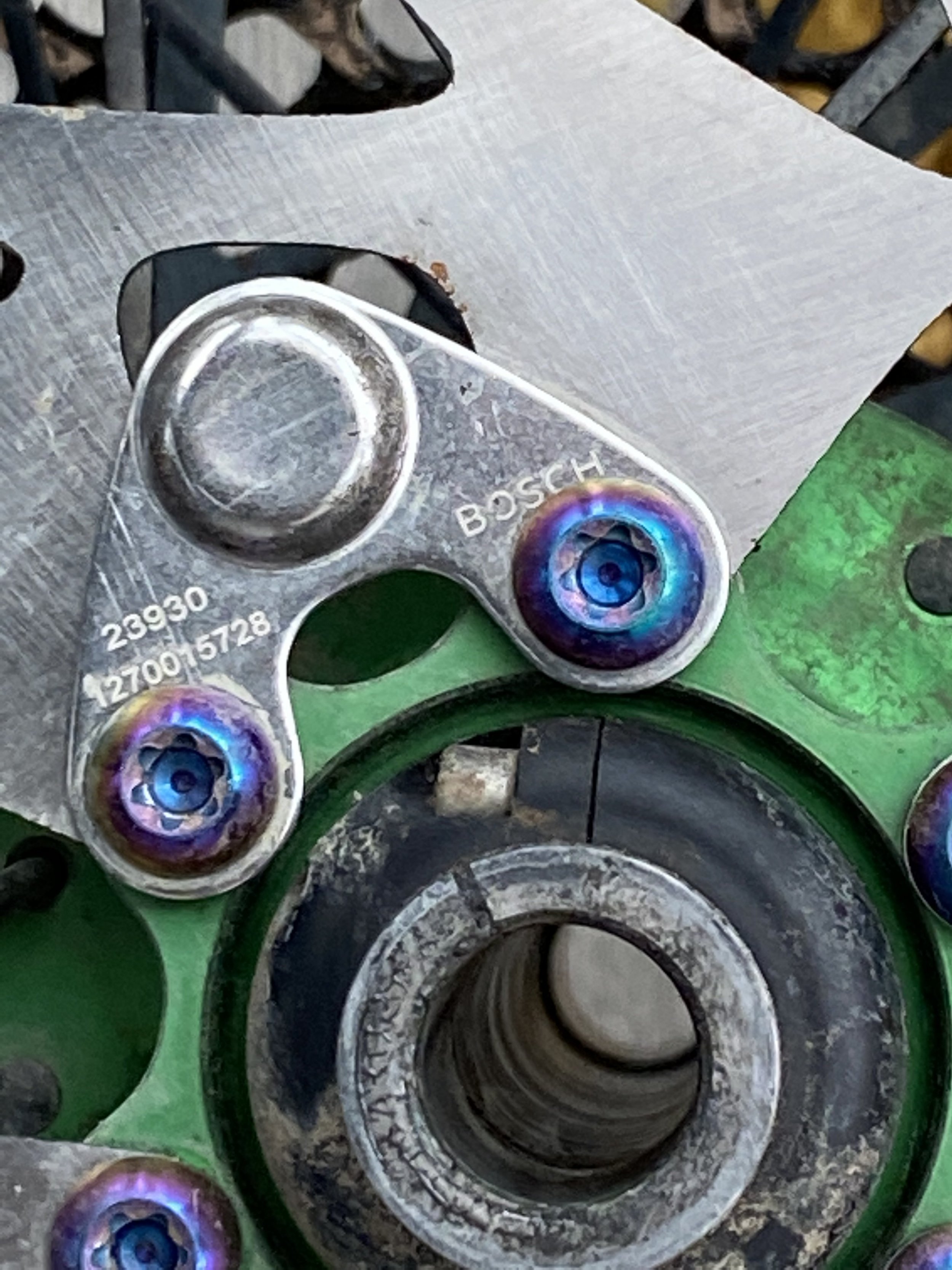
I attach a couple of pics of my speed sensor in frame and the simple magnet on the rotor.

Look forward to your reply & thx again for your design you’ve shared with everyone for no gain to yourself so far.

39A433FD-C0DC-487C-8672-A963D56C5050.jpeg 856A8731-92D1-4489-A429-C64DA34E821C.jpeg
 

BeBiker

Active member
Aug 26, 2020
700
421
Belgium
For these systems with external sensor there are multiple solutions on the market.

If you want to use and modify the DIY solution of this tread, you could relocate your sensor and put it close to the coil, or modify the coil output and feed it directly to the connector on the motor.

Other people mentioned the system with internal sensor will not work with an external sensor, I suspect the other way around too.
Often in such mass production systems the PCB and Software is the same, but depending on the requests some components are not populated and some modules are not activated in the firmware.
 

Uktonyb77

New Member
Feb 19, 2023
34
24
Uk
Yes I was thinking off modifying simply the coil you refer to as already being there but wouldn’t know where to start.

I realise there are other solutions on the market but two other riders whom I ride with that also have the Bosch smart system have had the usual motor issues then have to mess around taking bikes into dealers to get the errors cleared. One was using the speedbox 1.0b and the other one was using the Peartune mso. Both had the same errors on there bikes and didn’t take things to extreme as there gearing didn’t allow. Top speed’s they were hitting were only 28/30mph under assist mainly only doing that on the fire trail slogs. Seems quite a mixed bag with solutions that work with the Bosch smart system. Some people have issues whilst some don’’T.

The solution offered by mega is keeping things simple and not really interfering with much else on the Bosch system other than manipulating the speed sensor. All these other kits have integrations into the controller etc so you can turn things on/off with the Bosch controls.

For me and I’m sure lots of others ; things like that are not needed. We just need to go a little faster mainly for flat sections as the 16mph cut off is just sad. Yes you can use your legs more sure :) but why when someone smart has a solution which will probably be less problematic than all the other companies cashing in on manufacturing and selling derestriction devices.

I could be very wrong and there’s plenty of users on aftermarket derestriction kits without issues at all. I guess it’s just a roll of the dice and keep your fingers crossed on every software update Bosch release in case they countermeasure the current derestriction chip offerings.

Hopefully someone on this forum has already made there own DIY solution for the bikes that have a simple in frame sensor and a magnet on the rotor. Maybe they will even be kind enough to share it ;)
 

Sander

Member
Dec 29, 2022
56
29
NL
Yes I was thinking off modifying simply the coil you refer to as already being there but wouldn’t know where to start.

I realise there are other solutions on the market but two other riders whom I ride with that also have the Bosch smart system have had the usual motor issues then have to mess around taking bikes into dealers to get the errors cleared. One was using the speedbox 1.0b and the other one was using the Peartune mso. Both had the same errors on there bikes and didn’t take things to extreme as there gearing didn’t allow. Top speed’s they were hitting were only 28/30mph under assist mainly only doing that on the fire trail slogs. Seems quite a mixed bag with solutions that work with the Bosch smart system. Some people have issues whilst some don’’T.

The solution offered by mega is keeping things simple and not really interfering with much else on the Bosch system other than manipulating the speed sensor. All these other kits have integrations into the controller etc so you can turn things on/off with the Bosch controls.

For me and I’m sure lots of others ; things like that are not needed. We just need to go a little faster mainly for flat sections as the 16mph cut off is just sad. Yes you can use your legs more sure :) but why when someone smart has a solution which will probably be less problematic than all the other companies cashing in on manufacturing and selling derestriction devices.

I could be very wrong and there’s plenty of users on aftermarket derestriction kits without issues at all. I guess it’s just a roll of the dice and keep your fingers crossed on every software update Bosch release in case they countermeasure the current derestriction chip offerings.

Hopefully someone on this forum has already made there own DIY solution for the bikes that have a simple in frame sensor and a magnet on the rotor. Maybe they will even be kind enough to share it ;)
Hi Uktonyb77,
With your external sensor and magnet on your rotor, you can easily make a Megabobra ;-) You can use your Bosch sensor by cutting the wire aprox. 10cm before entering the motor. Rewire the wire with some connector. Use the same connector to connect it to your sensor input on your Arduino. Purcasethe low power cable from Bosch like mentioned before and go to a Bosch dealer to open the low Power port on your motor. Buy a electro magnet or wind your own et voila! :) And if you are going to bike in a country where the fines a to high, you remove the speedsensor from the Arduino and connect it to the original speedsensor wire where you made a cut and placed a connector.
 

Sander

Member
Dec 29, 2022
56
29
NL
Yes I was thinking off modifying simply the coil you refer to as already being there but wouldn’t know where to start.

I realise there are other solutions on the market but two other riders whom I ride with that also have the Bosch smart system have had the usual motor issues then have to mess around taking bikes into dealers to get the errors cleared. One was using the speedbox 1.0b and the other one was using the Peartune mso. Both had the same errors on there bikes and didn’t take things to extreme as there gearing didn’t allow. Top speed’s they were hitting were only 28/30mph under assist mainly only doing that on the fire trail slogs. Seems quite a mixed bag with solutions that work with the Bosch smart system. Some people have issues whilst some don’’T.

The solution offered by mega is keeping things simple and not really interfering with much else on the Bosch system other than manipulating the speed sensor. All these other kits have integrations into the controller etc so you can turn things on/off with the Bosch controls.

For me and I’m sure lots of others ; things like that are not needed. We just need to go a little faster mainly for flat sections as the 16mph cut off is just sad. Yes you can use your legs more sure :) but why when someone smart has a solution which will probably be less problematic than all the other companies cashing in on manufacturing and selling derestriction devices.

I could be very wrong and there’s plenty of users on aftermarket derestriction kits without issues at all. I guess it’s just a roll of the dice and keep your fingers crossed on every software update Bosch release in case they countermeasure the current derestriction chip offerings.

Hopefully someone on this forum has already made there own DIY solution for the bikes that have a simple in frame sensor and a magnet on the rotor. Maybe they will even be kind enough to share it ;)
Megabobra and I have an internal speedsensor, but we by passed it by making the configuration you already have :)
 

Uktonyb77

New Member
Feb 19, 2023
34
24
Uk
Thx for your response sander. Excuse my lack of knowledge but where would I be placing the electromagnet on my system ? In terms of winding my own would it still be to the same spec as you guys constructed with the gauge of wire and length around the 25mm pvc X amount of times ??? Or as I’m looking to use the in frame speedsensor already on the bike would tolerances of anything be different from a technical perspective ?

I’m assuming of course the mega solution was built to mimick the rim magnet specification and then manipulate this with the multiplier ? So if I’ve never had a rim magnet on the bike and only the one in frame speed sensor I guess I’m asking would everything be the same in terms of how the electromagnet would be setup ?

Thx again
 

Sander

Member
Dec 29, 2022
56
29
NL
Thx for your response sander. Excuse my lack of knowledge but where would I be placing the electromagnet on my system ? In terms of winding my own would it still be to the same spec as you guys constructed with the gauge of wire and length around the 25mm pvc X amount of times ??? Or as I’m looking to use the in frame speedsensor already on the bike would tolerances of anything be different from a technical perspective ?

I’m assuming of course the mega solution was built to mimick the rim magnet specification and then manipulate this with the multiplier ? So if I’ve never had a rim magnet on the bike and only the one in frame speed sensor I guess I’m asking would everything be the same in terms of how the electromagnet would be setup ?

Thx again
You are right! Hmmmm, let me think :cool:
 

Sander

Member
Dec 29, 2022
56
29
NL
Thx for your response sander. Excuse my lack of knowledge but where would I be placing the electromagnet on my system ? In terms of winding my own would it still be to the same spec as you guys constructed with the gauge of wire and length around the 25mm pvc X amount of times ??? Or as I’m looking to use the in frame speedsensor already on the bike would tolerances of anything be different from a technical perspective ?

I’m assuming of course the mega solution was built to mimick the rim magnet specification and then manipulate this with the multiplier ? So if I’ve never had a rim magnet on the bike and only the one in frame speed sensor I guess I’m asking would everything be the same in terms of how the electromagnet would be setup ?

Thx again
Maybe, that if we instead of firing the electro magnet we could attach a another reed switch that connects the original input speedsensor. But then you are back to the point Bebiker mentioned: a third party device. I believe it's not possible, if you're running the smart system, to go to a Bosch dealer and swittch the system to an internal speedsensor.......hmmm.
 

Uktonyb77

New Member
Feb 19, 2023
34
24
Uk
Again excuse the ignorance but looking at how the third party devices function utilising existing speed sensors already fitted in frames the pcb board they are using most also be manipulating the speedsensor with some sort of code again utilising a multiplier of sorts. I get they have more features like being able to turn on/off via the Bosch controls and displaying / representing the speed differently after the legal limit and following a bizarre logic of representation on screen. Really for me I’m not bothered for that.

So could the small boards you guys are using have code written to utilise existing in frame sensors which then enter the board as the actual speed given at the sensor , then manipulated with code and outputted from the board with the manipulated figure back into the speed sensor connector on the motor ?

In reality that’s got to be pretty much how all these 3rd party units are doing it perhaps.

Mega has made a working solution with his own knowledge and know how with electronics and coding etc but some of us are truly not that gifted :)

But yes I could take a lottery at a third party device but would be more rewarding to make my own especially if a simple solution of sorts was available.

Thx for giving it some thought sander
 

Sander

Member
Dec 29, 2022
56
29
NL
Again excuse the ignorance but looking at how the third party devices function utilising existing speed sensors already fitted in frames the pcb board they are using most also be manipulating the speedsensor with some sort of code again utilising a multiplier of sorts. I get they have more features like being able to turn on/off via the Bosch controls and displaying / representing the speed differently after the legal limit and following a bizarre logic of representation on screen. Really for me I’m not bothered for that.

So could the small boards you guys are using have code written to utilise existing in frame sensors which then enter the board as the actual speed given at the sensor , then manipulated with code and outputted from the board with the manipulated figure back into the speed sensor connector on the motor ?

In reality that’s got to be pretty much how all these 3rd party units are doing it perhaps.

Mega has made a working solution with his own knowledge and know how with electronics and coding etc but some of us are truly not that gifted :)

But yes I could take a lottery at a third party device but would be more rewarding to make my own especially if a simple solution of sorts was available.

Thx for giving it some thought sander
Maybe if you use a second reed switch: a bosch speedsendor plugged into the motor and let the electromagnet fire this reed switch? Or maybe there is a way to attach the cuted wires from the speedsensor (that is still plugged into motor) to the Arduino and the Arduino will tell the port is on or off. Something like that? Megabobra?😎😉
 

megabobra

Active member
Jul 24, 2022
269
271
Australia
Maybe if you use a second reed switch: a bosch speedsendor plugged into the motor and let the electromagnet fire this reed switch? Or maybe there is a way to attach the cuted wires from the speedsensor (that is still plugged into motor) to the Arduino and the Arduino will tell the port is on or off. Something like that? Megabobra?😎😉

Hi guys,
I think the easiest way to set this up would just be to cut the existing speed sensor cable between motor and wheel and insert the Arduino in the middle of it. From the wheel end, this would look exactly the same as the current setup as in the tutorial: reed switch on the wheel feeds an input port on the Arduino.

On the motor end, I don't see why we couldn't use the arduino to short the speed sensor wires as if it was done by the reed switch and magnet. You'd have to experiment, but could we not just drop the wires from the motor's speed sensor directly in place of the electromagnet's output, transistor and all? Only change would be disconnect the 5v feed from the transistor's collector leg. I've attached an updated schematic.

This way each time we fire the transistor we'd short the speed sensor. Might be that simple?

But we'd first need to check the behaviour of the existing speed sensor. Ideally there would be only two wires. Then to confirm there's no other smarts in the sensor itself, just measure the resistance across the sensor both when it's in front of the magnet and when it's not. If there's just open circuit when no magnet and closed circuit (with minimal resistance) with magnet, then I'd say good to go?

But surely it can't be that easy? :)

Schematic Update.jpg
 

Sander

Member
Dec 29, 2022
56
29
NL
Hi guys,
I think the easiest way to set this up would just be to cut the existing speed sensor cable between motor and wheel and insert the Arduino in the middle of it. From the wheel end, this would look exactly the same as the current setup as in the tutorial: reed switch on the wheel feeds an input port on the Arduino.

On the motor end, I don't see why we couldn't use the arduino to short the speed sensor wires as if it was done by the reed switch and magnet. You'd have to experiment, but could we not just drop the wires from the motor's speed sensor directly in place of the electromagnet's output, transistor and all? Only change would be disconnect the 5v feed from the transistor's collector leg. I've attached an updated schematic.

This way each time we fire the transistor we'd short the speed sensor. Might be that simple?

But we'd first need to check the behaviour of the existing speed sensor. Ideally there would be only two wires. Then to confirm there's no other smarts in the sensor itself, just measure the resistance across the sensor both when it's in front of the magnet and when it's not. If there's just open circuit when no magnet and closed circuit (with minimal resistance) with magnet, then I'd say good to go?

But surely it can't be that easy? :)

View attachment 109269
I have cut the original Bosch slim sensor: only 2 wires. Check!
 

Uktonyb77

New Member
Feb 19, 2023
34
24
Uk
I will take apart stuff over weekend as will have more time. A little anxious of cutting the speed sensor cable to be honest though. Is there not a cable I could pre purchase that would fit into the speed cable ( once it’s plug is removed from the motor ) sort of creating a link wire of sorts ?? That way if all fails I can still put the original speed sensor cable back into the motor ?

If it is as explained a simple open / closed circuit scenario as the magnet passes the current in frame sensor I can test this with a simple continuity test on the meter. Are there any other readings I should be looking to collect whilst things are exposed ?

This may seem a little thick but when you refer to the reed switch in your setup isn’t my speed sensor that’s currently in frame doing the same job ? Again I’m not a scientist or claim to be one :)

Thx again
Tony.
 

Ark

Active member
Mar 8, 2023
467
395
Newcastle Upon Tyne
You guys don't worry about triggering perma limp mode and needing to go a dealer?
Even the temporary limp mode is 90 minutes riding according to the bosch dealer service manual.
I still don't get why the manufactures are obsessed with it... there's plenty of things you can buy and use illegally and they don't go to ridiculous lengths to stop it...
Even a normal analogue bike can break the speed limit.. why not just restrict the gearing to 20mph on bikes....
none of it makes any sense to me. I know the bosch manual claims its to stop law suits against LBS but that sounds like utter rubbish and clutching at straws to try and enable their "Motor as a service" model
 

Uktonyb77

New Member
Feb 19, 2023
34
24
Uk
I of course worry about limp mode etc. my bike is only 2 months old and has the Bosch race motor so I’m a little concerned of messing things up. But if I don’t try I won’t know. 16mph cut in the Uk is awful especially when your riding to and from the trails on fire roads or country lanes etc. Then there is ofcourse them flat sections of singletrack that at 16mph is alright but could be more fun with more speed.

Yes again I could just go buy a 3rd party readily available one but like a challenge and from mega’s design work there’s nothing else being interfered with in the Bosch smart system other than the speed reported. Who knows what all these other 3rd party devices are doing by also hooking into the system controller on the Bosch smart.

Keeping it simple to do what should be a simple ask is fine with me. I mean why would you want to turn a derestriction off anyway what’s it’s installed in the system ? Also in terms of software updating in future etc with megas solution it’s not actually doing anything by way of talking back to the Bosch Controller when the wheel isn’t moving. All these other 3rd party ones are hooked into the Bosch system. So again I suspect Bosch could detect this quite easily and then roll out a future update which then kills the 3rd party devices from working in future. & yes of course you can unplug or turn off a 3rd party one prior to updating firmware ; but again it’s more faff
 

megabobra

Active member
Jul 24, 2022
269
271
Australia
I will take apart stuff over weekend as will have more time. A little anxious of cutting the speed sensor cable to be honest though. Is there not a cable I could pre purchase that would fit into the speed cable ( once it’s plug is removed from the motor ) sort of creating a link wire of sorts ?? That way if all fails I can still put the original speed sensor cable back into the motor ?

If it is as explained a simple open / closed circuit scenario as the magnet passes the current in frame sensor I can test this with a simple continuity test on the meter. Are there any other readings I should be looking to collect whilst things are exposed ?

This may seem a little thick but when you refer to the reed switch in your setup isn’t my speed sensor that’s currently in frame doing the same job ? Again I’m not a scientist or claim to be one :)

Thx again
Tony.

Hi Tony,
Yep I bet you could avoid cutting the speed sensor. You'd need to track down the same plug that the sensor uses to get into the motor and then just use that as you say to wire in the arduino. Not sure if maybe it's the same plug as aux power cable I used above? The aux cable goes into the green power port - see if the speed sensor will fit in there? I think it's just the resistance when open and closed you should check on the existing speed sensor; just check form the port end if you can get some probes in there.

Otherwise of course just buy a spare speed sensor, might be this one? Bosch Speed Sensor Slim - Smart System

Yes in my example above, the reed switch in your case is actually just your speed sensor, so no need for a second reed switch.

Finally, if you'd prefer to just leave everything as is and setup with least impact to the existing system, why not just build the original device with electromagnet and place the magnet against your speed sensor? Just reposition your speed sensor to somewhere in your downtube with the electromagnet, and instead place the reed switch connected to the ardunio at the wheel.

Thoughts?
 

EMTB Forums

Since 2018

The World's largest electric mountain bike community.

561K
Messages
28,436
Members
Join Our Community

Latest articles


Top