Thank you Guys for such precise assembly details. I also thing about building by myself bike using E55 frame and have just ordered motor. Searching for info regarding E55 I noticed one element that is not in your intructions/photos. It’s something like plate (metal? plastic?), an element that is like a cover protecting the battery inside the frame and it should comes with the frame.


You are using an out of date browser. It may not display this or other websites correctly.
You should upgrade or use an alternative browser.
You should upgrade or use an alternative browser.
TQFreak's Dengfu E55 Build Thread
- Thread starter TQFreak
- Start date
- Thread starter
- #122
Yes, the details are hereDoes somebody know the exact shock bushings sizes for e55 frame?
TQFreak's Dengfu E55 Build Thread
A separate thread for the build of this bike from the main E55/56 thread : https://www.emtbforums.com/threads/dengfu-e55-emtb-and-e56-fat-bike-new-selection-of-diy-frame.31400/ My 17" Dengfu E55 frame is arrived and it looks amazing! The box with the frame Everything is packed very well...
- Thread starter
- #123
Alright, I have finished the new 52V 80A battery and wiring harness and finally tested my 3000W Innotrace X1 at full power. That thing is a monster! I was able to reach 40 mph on flat with not so much effort and that thing can coast 30-35 mph on flat effortlessly. It can easily keep up with traffic of flat area in 35 mph speed limit zone and I was even able to keep up with traffic uphill in 35 mph zone. Wow!
And I can confirm that thing pulls 3000W maximum - I installed Jiabaida JBD SP17S005 BMS (80A version), that BMS has integrated Bluetooth and mobile phone application and I checked the wattage it pulled out of the battery with my phone at full throttle.
The only thing is that motor pulls at full wattage maybe for 30-60 seconds continuously and then it reduces the power for some time (I guess for cool down) so full power it not 100% duty time.
The motor warms up to for maybe 60 deg Celsius or so externally, not crazy hot.
Here is the list of materials:
First of all I purchased the battery case with cells holders and battery mounding interfaces here


The BMS is 80A Jiabaida JBD SP17S005 (programmable with integrated Bluetooth) I purchased here
 www.greenbikekit.com

The battery cells are 21700 Samsung 50S 21700 5000mAh 25A I purchased here

 www.18650batterystore.com

The positive terminal 21700 battery insulation rings I purchased here

Differed sizes of Kapton tape (1/4", 1/2", 3/4", 1" and 2") I purchased here

Different gauges (8AWG, 12AWG and 16AWG) of red and black silicone insulation wires I purchased here
https://www.amazon.com/dp/B017TFR664?psc=1&ref=ppx_yo2ov_dt_b_product_details

A roll of 0.2mm thick 10mm wide pure nickel strips I purchased here

A roll of 5" x 25' x 0.010" thick fish paper I purchased here

A roll of 180mm wire battery pack heat shrink I purchased here

A high current plug (Amass XT90H) to connect the battery mount cable and the motor I purchased here
 www.greenbikekit.com

Terminal kit for the frame charging cable (JST-SM2.5) I purchased here

Connector for the frame battery switch button cable between the switch cable and the battery mount cable (XT30) I purchased here

To connect the frame battery switch button cable to the battery (between the battery mount and the battery) I purchased two different pogo pins to fabricate a custom connector out of those

 www.mcmaster.com

 www.mcmaster.com


To connect the BMS on/off switch leads inside the battery to the external terminals I used a couple of AMP 66399-4 terminals

Sealant adhesive for the terminals (3M fast cure 5200) I purchased here

To fuse the main power discharge I purchased two MAXI fuse terminals

To fuse the charge wires and the battery level indicator I purchased a couple of MINI fuse holders

To fuse the main power discharge I purchased a 80A 58V MAXI fuse
To fuse the charge and battery level indicator wires I purchased a couple of 7.5A 58V MINI fuses


A thin silicone strip with adhesive layer to snug the battery back in battery case and to provide shock absorption I purchased here

To connect the flange cap of the battery case with charging port and battery level indicator with 20-22 AWG wires with TXL insulation I used Molex Nicro-Fit 3.0 terminals parts (Molex 430310008 male terminals, Molex 430300008 female terminals, Molex 430200409 4 circuits male terminals housing, Molex 430250400 4 circuits female terminals housing).


I also used some 20AWG and 22AWG TXL insulation automotive wires, assortment of different sizes of heat shrink tubes (with hot melt glue leaning and without), silver lead alloy solder and some another components I did not track.
And I can confirm that thing pulls 3000W maximum - I installed Jiabaida JBD SP17S005 BMS (80A version), that BMS has integrated Bluetooth and mobile phone application and I checked the wattage it pulled out of the battery with my phone at full throttle.
The only thing is that motor pulls at full wattage maybe for 30-60 seconds continuously and then it reduces the power for some time (I guess for cool down) so full power it not 100% duty time.
The motor warms up to for maybe 60 deg Celsius or so externally, not crazy hot.
Here is the list of materials:
First of all I purchased the battery case with cells holders and battery mounding interfaces here
The BMS is 80A Jiabaida JBD SP17S005 (programmable with integrated Bluetooth) I purchased here
Smart BMS for 10S 11S 12S 13S 14S 15S 16S 17S 48V 52V 40A 60A 80A with small size with bluetooth software-Greenbikekit.com BBS, ebike batteries, Bafang M620, Bafang M600, Bafang M500, Bafang M510, KT controller with display-GreenBikeKit.com
Smart battery BMS for 10s, 11s, 12s, 13S 14S 15s, 16s, 17s, 48V 52V 80A 40A 20A 60A with small size/smart BMS software
The battery cells are 21700 Samsung 50S 21700 5000mAh 25A I purchased here

Samsung 50S 21700 5000mAh 25A Battery
Experience high performance and reliability with the Samsung 50S 21700 5000mAh 25A battery. Rechargeable and suitable for various applications. Buy now!
The positive terminal 21700 battery insulation rings I purchased here
Differed sizes of Kapton tape (1/4", 1/2", 3/4", 1" and 2") I purchased here
Different gauges (8AWG, 12AWG and 16AWG) of red and black silicone insulation wires I purchased here
https://www.amazon.com/dp/B017TFR664?psc=1&ref=ppx_yo2ov_dt_b_product_details
A roll of 0.2mm thick 10mm wide pure nickel strips I purchased here
A roll of 5" x 25' x 0.010" thick fish paper I purchased here
A roll of 180mm wire battery pack heat shrink I purchased here
A high current plug (Amass XT90H) to connect the battery mount cable and the motor I purchased here
Amass XT90H RC battery connector with large current-greenbikekit.com BBS, ebike batteries, Bafang M620, Bafang M600, Bafang M500, Bafang M510, KT controller with display-GreenBikeKit.com
Amass connector XT90 for RC battery, car battery or ebike battery. This connector is small, but it can bear larger current.
Terminal kit for the frame charging cable (JST-SM2.5) I purchased here
Connector for the frame battery switch button cable between the switch cable and the battery mount cable (XT30) I purchased here
To connect the frame battery switch button cable to the battery (between the battery mount and the battery) I purchased two different pogo pins to fabricate a custom connector out of those
McMaster-Carr
McMaster-Carr is the complete source for your plant with over 595,000 products. 98% of products ordered ship from stock and deliver same or next day.
McMaster-Carr
McMaster-Carr is the complete source for your plant with over 595,000 products. 98% of products ordered ship from stock and deliver same or next day.
To connect the BMS on/off switch leads inside the battery to the external terminals I used a couple of AMP 66399-4 terminals
Sealant adhesive for the terminals (3M fast cure 5200) I purchased here
To fuse the main power discharge I purchased two MAXI fuse terminals
To fuse the charge wires and the battery level indicator I purchased a couple of MINI fuse holders
To fuse the main power discharge I purchased a 80A 58V MAXI fuse
To fuse the charge and battery level indicator wires I purchased a couple of 7.5A 58V MINI fuses
A thin silicone strip with adhesive layer to snug the battery back in battery case and to provide shock absorption I purchased here
To connect the flange cap of the battery case with charging port and battery level indicator with 20-22 AWG wires with TXL insulation I used Molex Nicro-Fit 3.0 terminals parts (Molex 430310008 male terminals, Molex 430300008 female terminals, Molex 430200409 4 circuits male terminals housing, Molex 430250400 4 circuits female terminals housing).
I also used some 20AWG and 22AWG TXL insulation automotive wires, assortment of different sizes of heat shrink tubes (with hot melt glue leaning and without), silver lead alloy solder and some another components I did not track.
Last edited:
- Thread starter
- #124
And here the custom high power output 80A 52V 14S4P 1050Wh battery pack. The pack is fully functional just like the stock battery (can be turned on and off with the button on the bike frame, has low voltage on the terminals when the battery is out of the frame for safety and to protect the battery terminals from sparking during connecting the battery to the frame and has fuses inside the battery pack for safety, has functional battery level indicator), plus has additional Bluetooth and programming features so you can monitor power consumption, set the battery charge level, monitor the battery and BMS temperatures, check the battery cells groups health, track the charging cycles, etc.).


Here is the modified battery mounting plate and custom harness


Here is the modified battery mounting plate and custom harness
Last edited:
- Thread starter
- #125
And here is the battery pack building process.
Unsolder the original wires on the BMS and solder them on opposite side of the board (for proper cable management)


You can see this 80A BMS uses two 10AWG silicone insulated wires on each side

Make sure all the battery cells have the same voltage withing +/-0.01 V. All the batteries in my case were withing +/-0.0005V

Stick the insulation rings on the positive terminals of the cells

Cut the battery holders to have space for the BMS

Here is the CAD model of what had to be built

Wrap the cells ends with masking tape so the cells fit snug into the cells frame

Assemble the cells into the holders


3D printed the BMS support out of ABS plastic

Attached the support to the BMS with double sided adhesive film

Masked the battery cells with masking tape wrapped the battery pack with 2 layers of 2" Kapton tape sticking the tape in between the cell with a plastic squeegee


Spot welded negative battery terminals out of two layers of 0.2mm thick 10mm wide nickel strips (I welded it on low adhesion conductive surface (on aluminum) with high power low timing setting on the welding machine to have good weld between the nickel strips). Bent one strip and the second kept flat. Soldered 12AWG silicone insulation wires to them. Insulated the solder joints with Kapton tape


Welded the first group negative terminal


I laser cut template to place the welding pencils in the correct place during welding


Welded next groups one by one following the rule to weld all series in the group first, them weld parallel

To flatten the nickel strips after cutting them with scissors I used a hard rubber roller on a plywood

Here is how I cut the balancing nickel terminals

Applied some solder on the terminal before welding to the battery

The balancing terminals are located on the left and the right side of the battery pack

Finished the positive battery terminals as the negative (3 silicone insulation wires 12AWG each attached to 2 layers of 0.2mm x 10mm nickel strips each)


And there you have it


Insulated the both sides of the battery back with a couple of layers of Kapton tape

Managed the balancing leads following the BMS wiring diagram


Trimmed the balancing leads

Soldered the balancing leads

Added programming leads, BMS switch leads and BMS temperature sensors leads


Trimmed and soldered the negative battery terminal leads to the BMS leads


Covered the joint with heat shrink tubes


Connected the balancing leads to the BMS and taped down the BMS in place

Unsolder the original wires on the BMS and solder them on opposite side of the board (for proper cable management)
You can see this 80A BMS uses two 10AWG silicone insulated wires on each side
Make sure all the battery cells have the same voltage withing +/-0.01 V. All the batteries in my case were withing +/-0.0005V
Stick the insulation rings on the positive terminals of the cells
Cut the battery holders to have space for the BMS
Here is the CAD model of what had to be built
Wrap the cells ends with masking tape so the cells fit snug into the cells frame
Assemble the cells into the holders
3D printed the BMS support out of ABS plastic
Attached the support to the BMS with double sided adhesive film
Masked the battery cells with masking tape wrapped the battery pack with 2 layers of 2" Kapton tape sticking the tape in between the cell with a plastic squeegee
Spot welded negative battery terminals out of two layers of 0.2mm thick 10mm wide nickel strips (I welded it on low adhesion conductive surface (on aluminum) with high power low timing setting on the welding machine to have good weld between the nickel strips). Bent one strip and the second kept flat. Soldered 12AWG silicone insulation wires to them. Insulated the solder joints with Kapton tape
Welded the first group negative terminal
I laser cut template to place the welding pencils in the correct place during welding
Welded next groups one by one following the rule to weld all series in the group first, them weld parallel
To flatten the nickel strips after cutting them with scissors I used a hard rubber roller on a plywood
Here is how I cut the balancing nickel terminals
Applied some solder on the terminal before welding to the battery
The balancing terminals are located on the left and the right side of the battery pack
Finished the positive battery terminals as the negative (3 silicone insulation wires 12AWG each attached to 2 layers of 0.2mm x 10mm nickel strips each)
And there you have it
Insulated the both sides of the battery back with a couple of layers of Kapton tape
Managed the balancing leads following the BMS wiring diagram
Trimmed the balancing leads
Soldered the balancing leads
Added programming leads, BMS switch leads and BMS temperature sensors leads
Trimmed and soldered the negative battery terminal leads to the BMS leads
Covered the joint with heat shrink tubes
Connected the balancing leads to the BMS and taped down the BMS in place
- Thread starter
- #126
Connected the BMS to the computer with programming cable and checked the BMS reads the series connections properly in the BMS program (first time I connected it was reading 12 series instead of 14 for some reason, I disconnected the balancing leads from BMS and connected them back to BMS and after this BMS started reading the series groups of cells properly.


Soldered 20AWG TXL wires to the BMS "B-" and "C-" and routed them to the positive side of the battery pack

Soldered 8AWG silicone insulation wire to the battery positive terminal leads

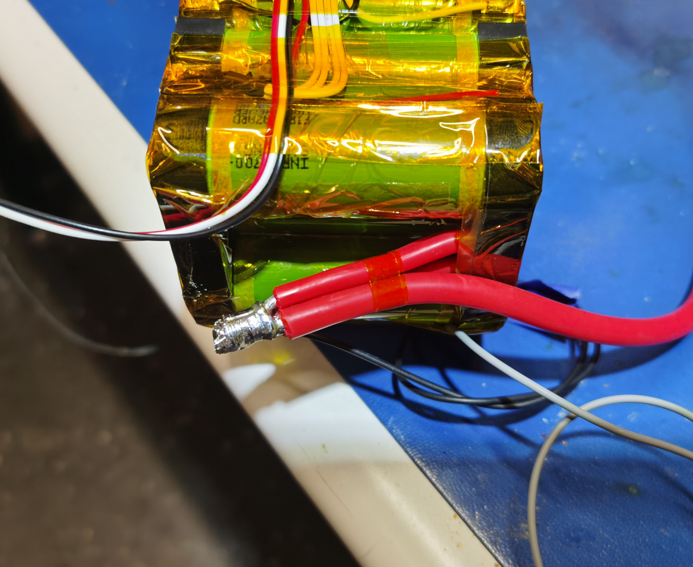
Trimmed the MAXI fuse terminals


Soldered a 8AWG wire to it


Soldered same way trimmed terminal to the 8AWG battery positive lead

Covered it with multiple heat shrink tubes sections

Cut a spacer out of fiberglass board and assembled the MAXI fuse receptacle with it using heat shrink tubes


Soldered the wires on the battery level indicator board different way to change the wires route and secured them hot melt glue and Kapton tape


Covered the board with some foam

Soldered the MINI fuse receptacle leads to the battery positive leads joint


Attached 7.5A MINI fuse to the receptacle, trimmed the receptacle output lead short and soldered 20AWG TXL wires to the receptacle lead for proper cable management (the receptacle leads are too thick)

Soldered wires to the charging port (battery positive from the 7.5A fuse and battery level indicator positive).


Trimmed the wires and attached the Molex terminals


Connected the wires from the battery (positive charge-level indicator, negative charge from BMS "C-", negative battery level from BMS "B-") to the mating Molex terminal


Connected the harness and checked the battery level works


Checked everything fits properly inside the battery cup


Cut foam spacers and a fiberglass board cover to protect the BMS terminals


Two layers of fish paper on each left and right sides and one on the top and one on the bottom. The corners where the balansing leads are soldered are protected with L-shaped fold of the fish paper from the sides


Trimmed the BMS "C-" leads and soldered 3 of 12AWG silicone insulation wires to those


Routed the 8AWG wire from the 80A fuse on the bottom of the battery to the battery terminal side and soldered 3 of 12AWG silicone insulation wires to it


Trimmed and soldered the 12AWG wires to the battery terminals


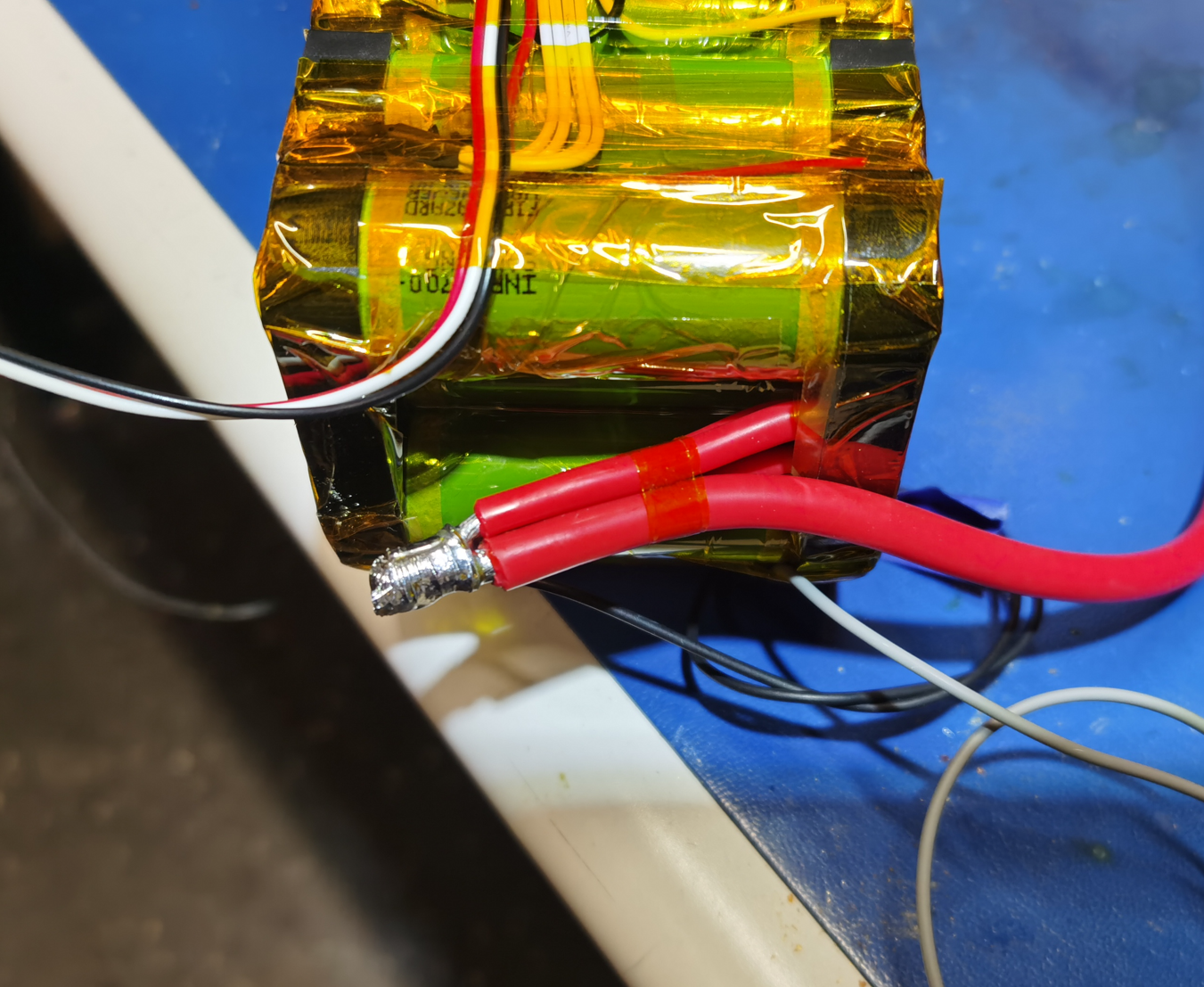
Soldered 20AWG TXL wires to the BMS "B-" and "C-" and routed them to the positive side of the battery pack
Soldered 8AWG silicone insulation wire to the battery positive terminal leads
Trimmed the MAXI fuse terminals
Soldered a 8AWG wire to it
Soldered same way trimmed terminal to the 8AWG battery positive lead
Covered it with multiple heat shrink tubes sections
Cut a spacer out of fiberglass board and assembled the MAXI fuse receptacle with it using heat shrink tubes
Soldered the wires on the battery level indicator board different way to change the wires route and secured them hot melt glue and Kapton tape
Covered the board with some foam
Soldered the MINI fuse receptacle leads to the battery positive leads joint
Attached 7.5A MINI fuse to the receptacle, trimmed the receptacle output lead short and soldered 20AWG TXL wires to the receptacle lead for proper cable management (the receptacle leads are too thick)
Soldered wires to the charging port (battery positive from the 7.5A fuse and battery level indicator positive).
Trimmed the wires and attached the Molex terminals
Connected the wires from the battery (positive charge-level indicator, negative charge from BMS "C-", negative battery level from BMS "B-") to the mating Molex terminal
Connected the harness and checked the battery level works
Checked everything fits properly inside the battery cup
Cut foam spacers and a fiberglass board cover to protect the BMS terminals
Two layers of fish paper on each left and right sides and one on the top and one on the bottom. The corners where the balansing leads are soldered are protected with L-shaped fold of the fish paper from the sides
Trimmed the BMS "C-" leads and soldered 3 of 12AWG silicone insulation wires to those
Routed the 8AWG wire from the 80A fuse on the bottom of the battery to the battery terminal side and soldered 3 of 12AWG silicone insulation wires to it
Trimmed and soldered the 12AWG wires to the battery terminals

- Thread starter
- #127
Here is the idea how the battery power cables are managed


The next step was to fabricate the interface for the battery BMS on/off switch
I teared the cup-pogo pins to use the cupped pins from it

Trimmed the pins

Drilled holes in the battery cover using laser cut template. The diameter of the holes maintains press-fit interface with the pins.


Chamfered the holes to match the pins heads shape

Trimmed a couple of AMP 66399-4 terminals short

These AMP terminals should fit the pins

Pressed the pins into the holes


Trimmed the BMS on/off switch leads and soldered the AMP terminals in those


Wrapped the battery with heat shrink wrap


Sticked the silicone strips in the battery bottom edjes

Covered the silicone strips with L-folded fish tape to protect it from tearing during sliding the battery back inside the battery aluminum case. I used 3M 77 spray adhesive to tack the fish tape in place


Sled the battery pack into the housing and tri the protective fish tape

Connected the indicator side cover to the battery

Sticked a piece of foam to the cover to support the battery pack inside the case

Applied some silicone adhesive sealant to the charging port connector back side to cover the opeinings

Attached the cover

Applied the sealant to the battery terminals

Attached the terminals to the battery lead

Added some foam for support and assembled the battery completely


And here you have it

Clipped the original Bafang m620 terminals off from the motor leads


Soldered high current XT90 terminals in the motor leads


And here you have it, how it supposed to be delivered from Innotrace but was not

The next step was to fabricate the interface for the battery BMS on/off switch
I teared the cup-pogo pins to use the cupped pins from it
Trimmed the pins
Drilled holes in the battery cover using laser cut template. The diameter of the holes maintains press-fit interface with the pins.
Chamfered the holes to match the pins heads shape
Trimmed a couple of AMP 66399-4 terminals short
These AMP terminals should fit the pins
Pressed the pins into the holes
Trimmed the BMS on/off switch leads and soldered the AMP terminals in those
Wrapped the battery with heat shrink wrap
Sticked the silicone strips in the battery bottom edjes
Covered the silicone strips with L-folded fish tape to protect it from tearing during sliding the battery back inside the battery aluminum case. I used 3M 77 spray adhesive to tack the fish tape in place
Sled the battery pack into the housing and tri the protective fish tape
Connected the indicator side cover to the battery
Sticked a piece of foam to the cover to support the battery pack inside the case
Applied some silicone adhesive sealant to the charging port connector back side to cover the opeinings
Attached the cover
Applied the sealant to the battery terminals
Attached the terminals to the battery lead
Added some foam for support and assembled the battery completely
And here you have it
Clipped the original Bafang m620 terminals off from the motor leads
Soldered high current XT90 terminals in the motor leads
And here you have it, how it supposed to be delivered from Innotrace but was not
- Thread starter
- #128
The I attached extra connectors for the battery on/off function.
In order to attach the new connector I drilled two holes in the battery bottom bracket

Tapped with M6

3D printed the connector housing out of ABS


Attached it to the bracket with a couple of 90 deg countersink M6 screws (those screws are maybe 15 mm long)


The pogo pins sit inside the housing

Those pogo-pins match the cup-head pins on the battery

Soldered 16AWG silicone insulation wires to the pins

Assembled the connector

Soldered the XT30 connector to it

 \
\
Soldered the 12AWG silicone insulation wires to the battery bottom bracket power connector


Crimped 20AWG TXL wires with JST-SM2.5 connector terminals

Finished the battery connector harness with attaching 8AWG silicone insulation wires to it, XT90 plug to mate with the motor, the 7.5A fuse with fuse holder and JST-SM2.5 connector for the charging leads.


Applies some sealant on the back side of the JST-SM2.5 connector

Attached the harness to the battery bottom bracket

Installed all this stuff into the bike frame


In order to attach the new connector I drilled two holes in the battery bottom bracket
Tapped with M6
3D printed the connector housing out of ABS
Attached it to the bracket with a couple of 90 deg countersink M6 screws (those screws are maybe 15 mm long)
The pogo pins sit inside the housing
Those pogo-pins match the cup-head pins on the battery
Soldered 16AWG silicone insulation wires to the pins
Assembled the connector
Soldered the XT30 connector to it
Soldered the 12AWG silicone insulation wires to the battery bottom bracket power connector
Crimped 20AWG TXL wires with JST-SM2.5 connector terminals
Finished the battery connector harness with attaching 8AWG silicone insulation wires to it, XT90 plug to mate with the motor, the 7.5A fuse with fuse holder and JST-SM2.5 connector for the charging leads.
Applies some sealant on the back side of the JST-SM2.5 connector
Attached the harness to the battery bottom bracket
Installed all this stuff into the bike frame
- Thread starter
- #129
Here are the CAD files of the pogo pins terminals housing and the JBD SP17S005 BMS support for 3D printing, the template to drill the battery cover for pogo pins and the template for the battery spot welding if you want to replicate what I did. I also attached the reverse engineered battery CAD model for reference if you want to use it.


Last edited:
Amazing write up, love all the detail you went into. I wanted to point over 60c on the exterior likely means the stator is quite warm and is throttling the power due to heat. On my bbshd I can get the stator to 90c while the exterior will be low 40's. After all the m620 is only rated at 1kw and you are pushing well over 3kw haha. And that xt90 imo is what the innotrace should come with not the xt60 they allow you to spec it with, so nice upgrade. Do you think 1000wh will be enough for that beast? I must admit after seeing your mock up in the other thread about fitting 140 cells I was hoping someone who do a custom battery and see how many watt hours they could cram in the E55. I'm thinking I will do a E55 build but I would like around 1250wh which should be easy I think
- Thread starter
- #131
I think 1000W is OK because of I feel 90% of time it uses below 1000W. But for me 3000W is necessary because of I commute on the road with some 35 mph speed limit sections and I need to keep up with traffic for safety reason.
I was thinking to fit bigger battery but that stock battery case is so convenient and I use about 50-60% of the full charge for one way commute of the existing battery so I decided to stick with the stock battery case.
I was thinking to fit bigger battery but that stock battery case is so convenient and I use about 50-60% of the full charge for one way commute of the existing battery so I decided to stick with the stock battery case.
I'm kindly asking for your help. I just got stuck in frame assembling. My 4 washers with 4 o-rings have been firmly inserted in the swingarm as from TQFreak photos. The big problem for me is to tighten it by screw as you can see from photos at any angle the clearance for the screw cannot be adjusted. Do you have any hint how to do ?
btw - I have got all the o-rings with dengfu frame
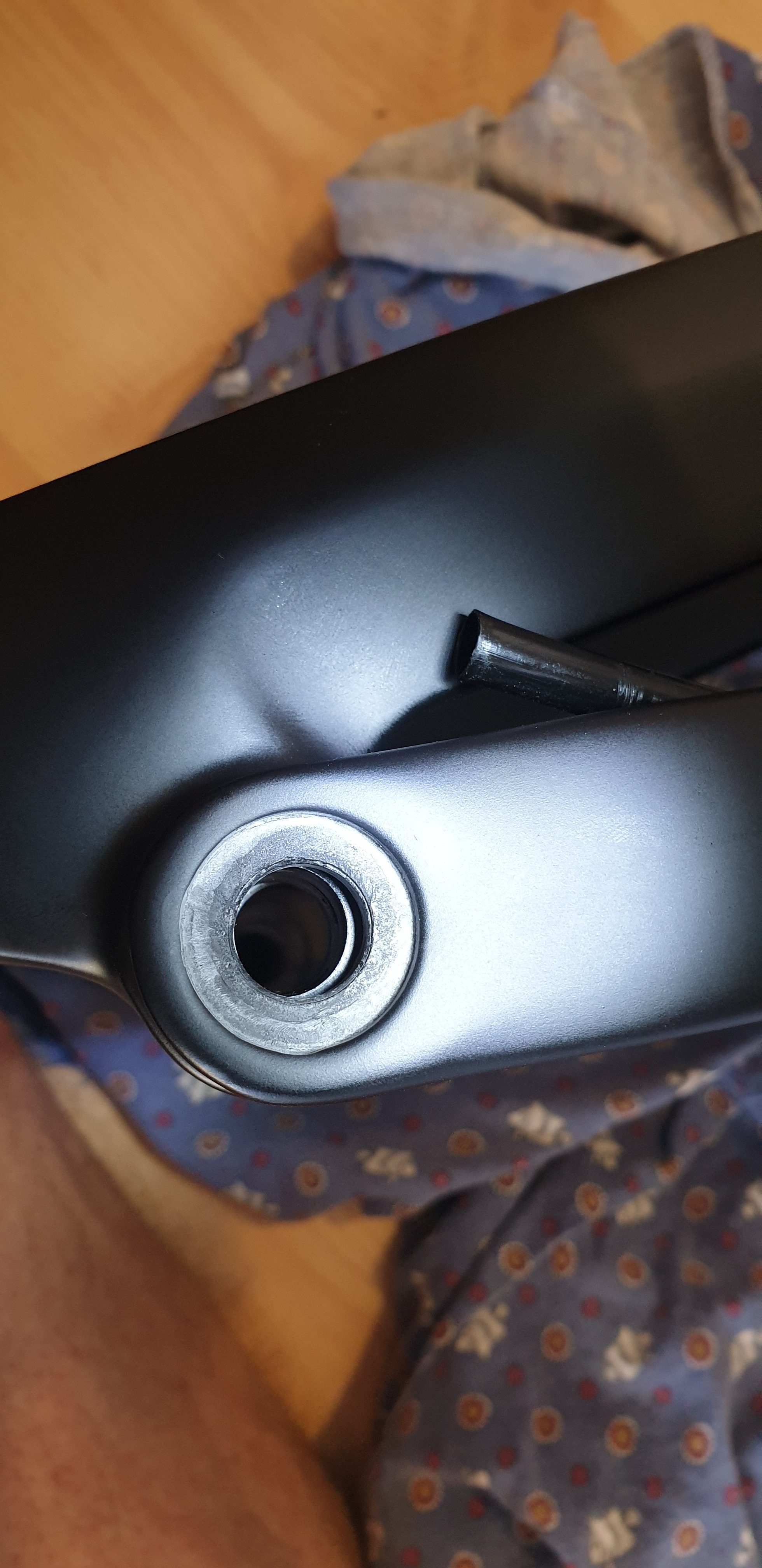
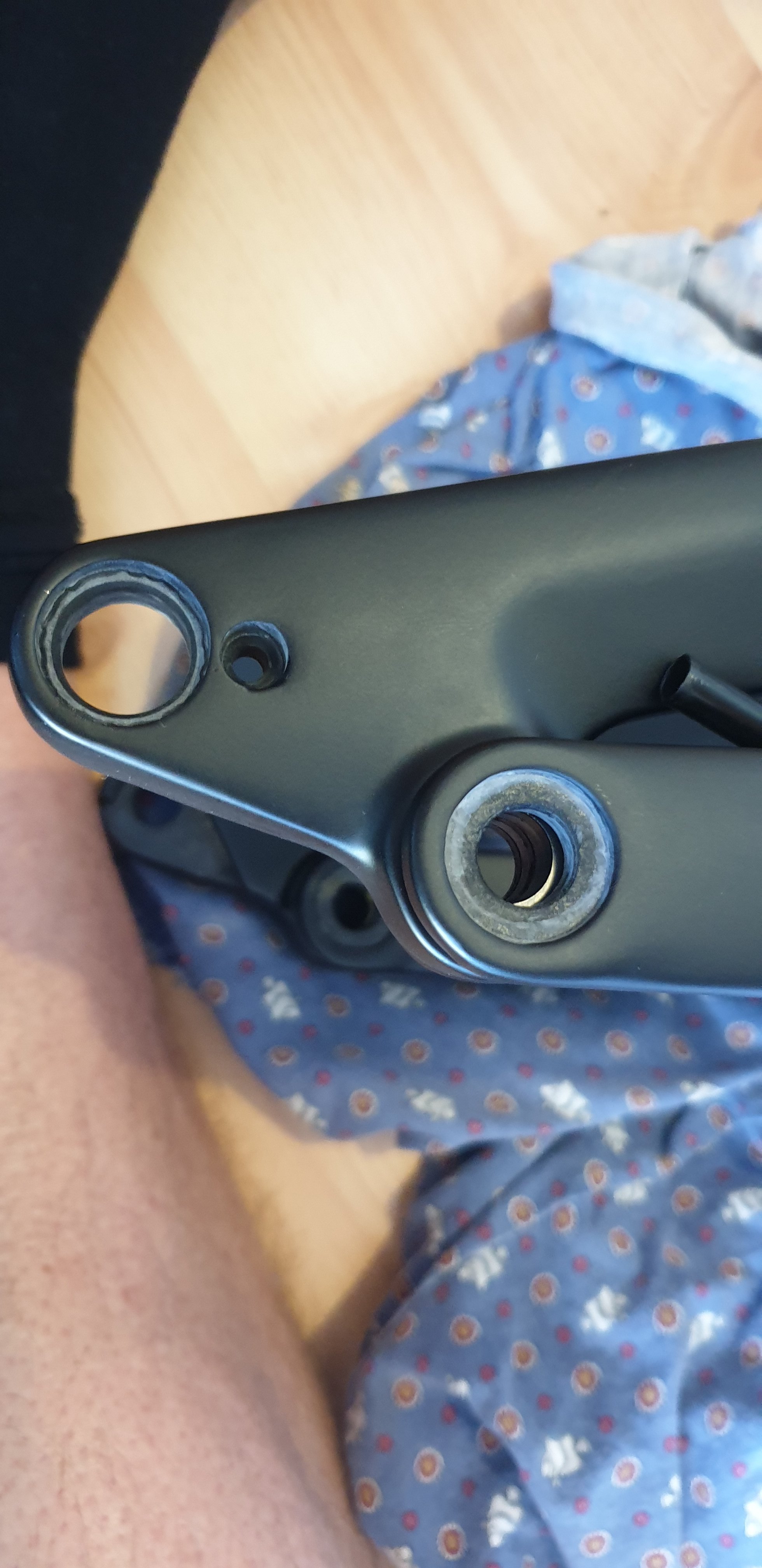
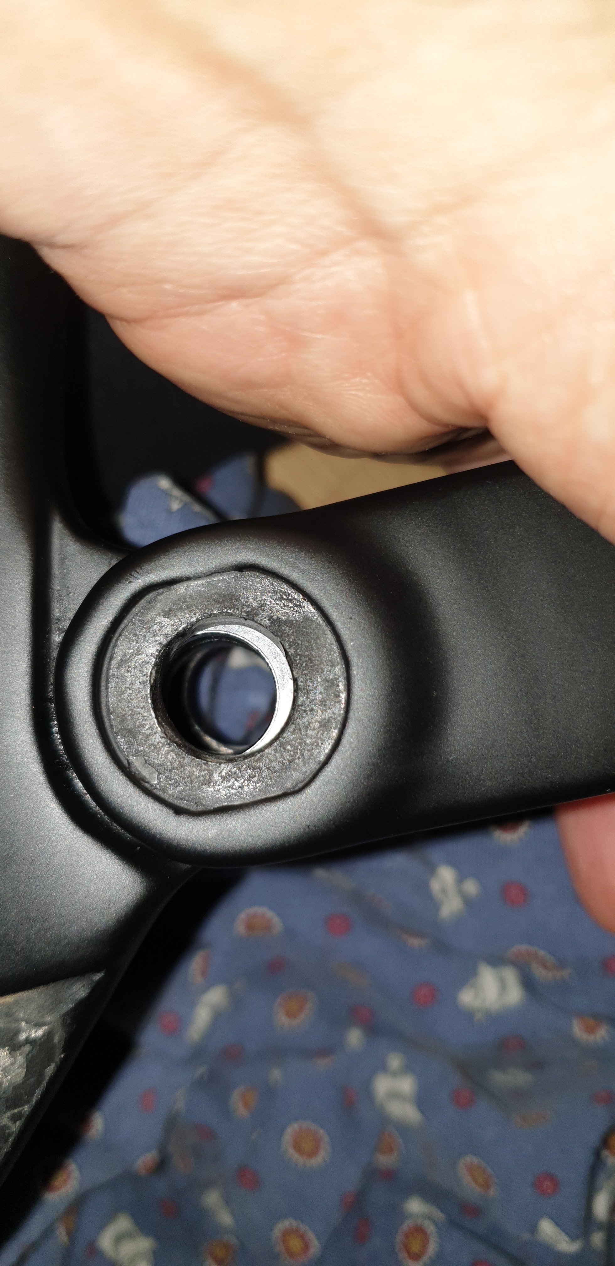
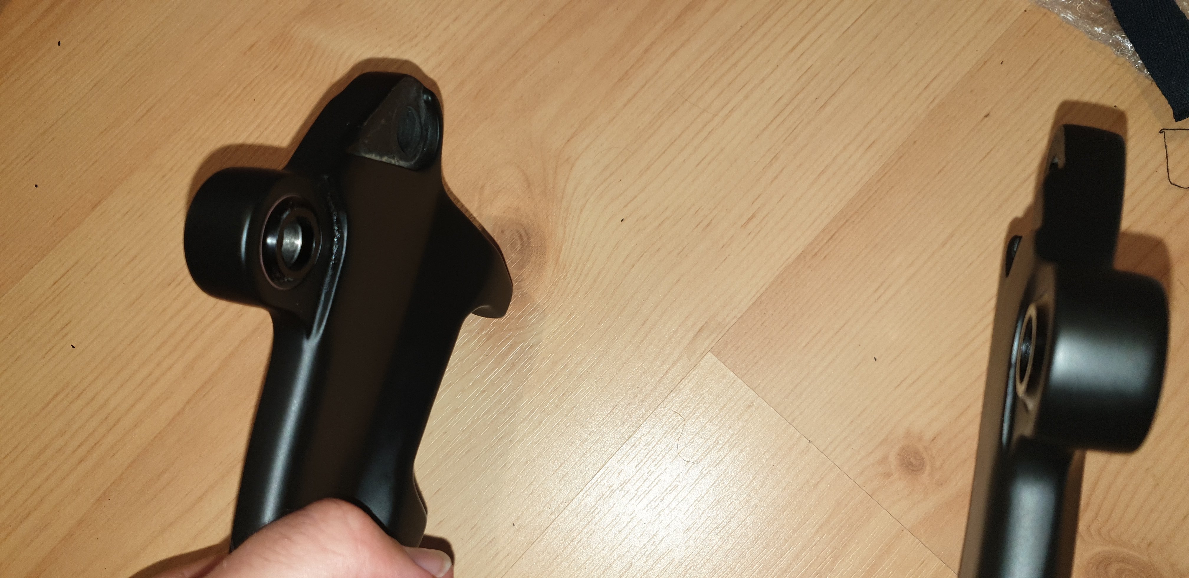
btw - I have got all the o-rings with dengfu frame


Thank you for your attention - OK finally I did It. I was afraid to use too much force but I managed to move elements to connect it by the screw.
BTW please look at the pictures: there are few differents in my frame set comparing to yours:
- it seems now to be even more finished inside
- instead of alu cable guides, they are now new made of plastic
- as I mentioned all the o-rings (also for headset) were added to my orginal set
- added cables between holes to help in assembing
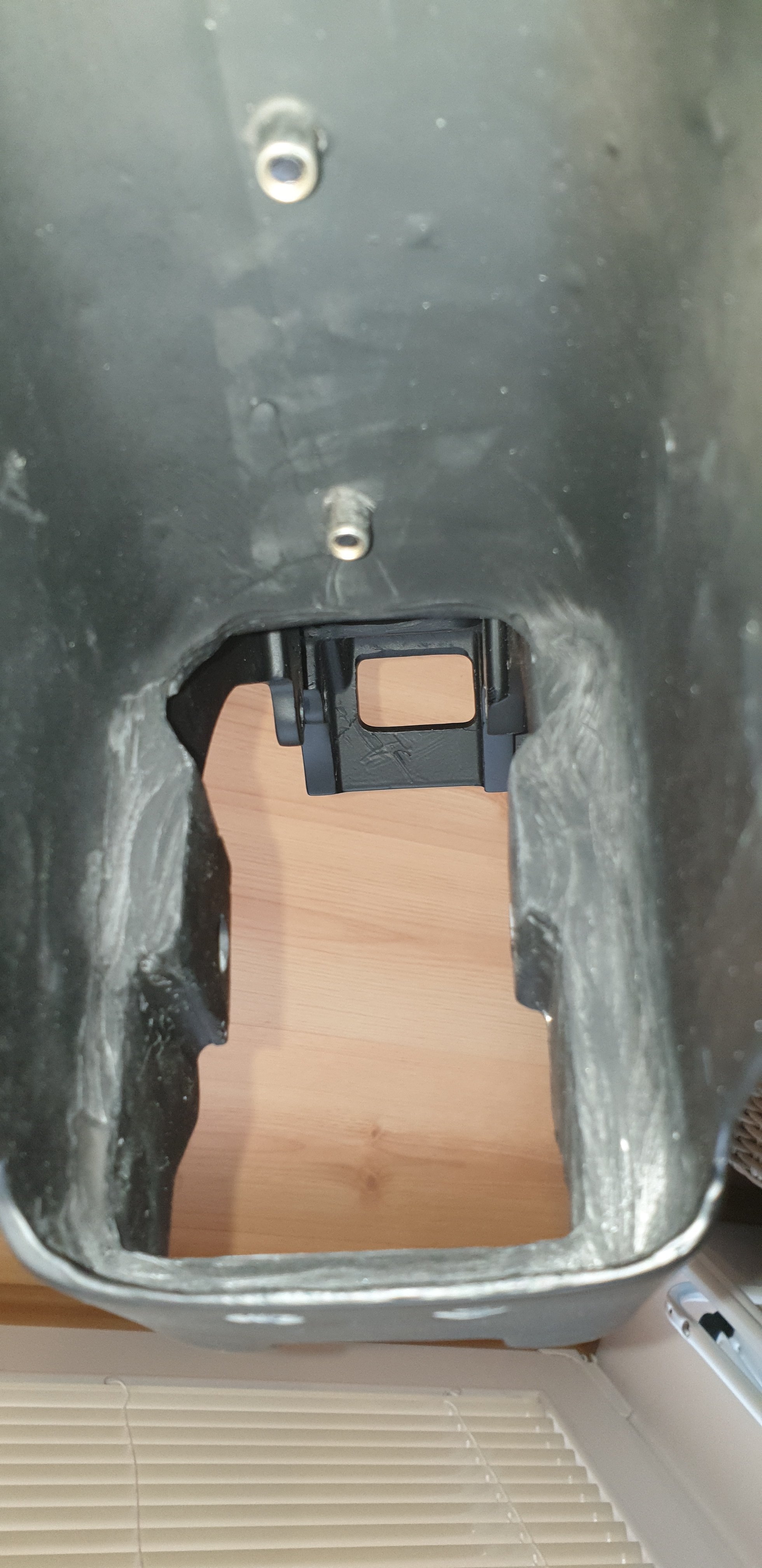
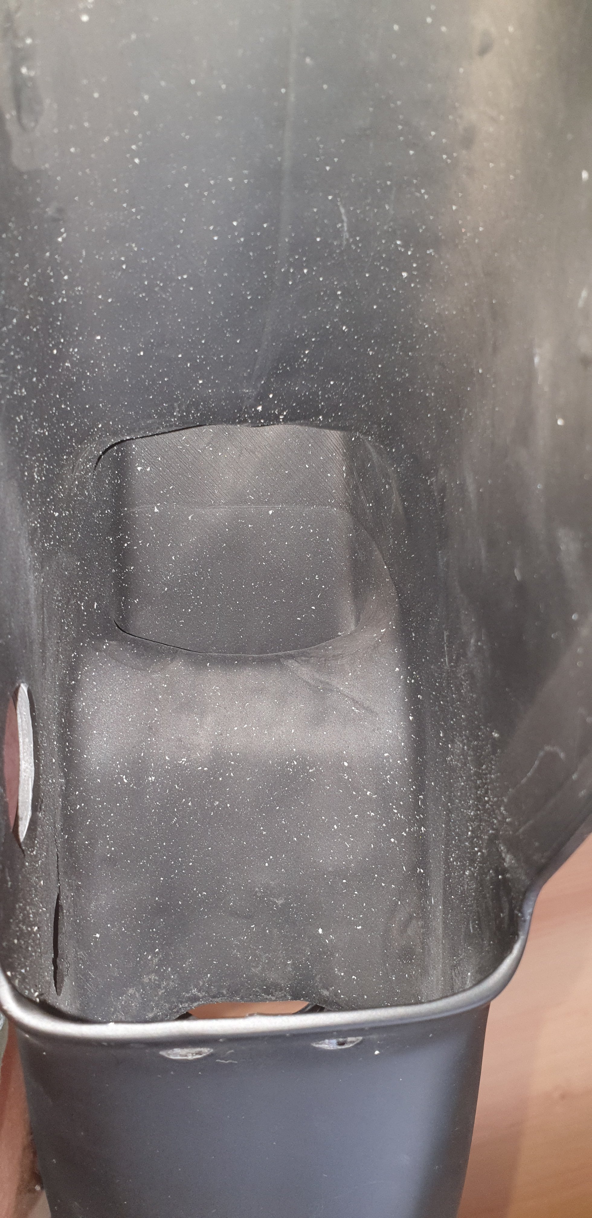
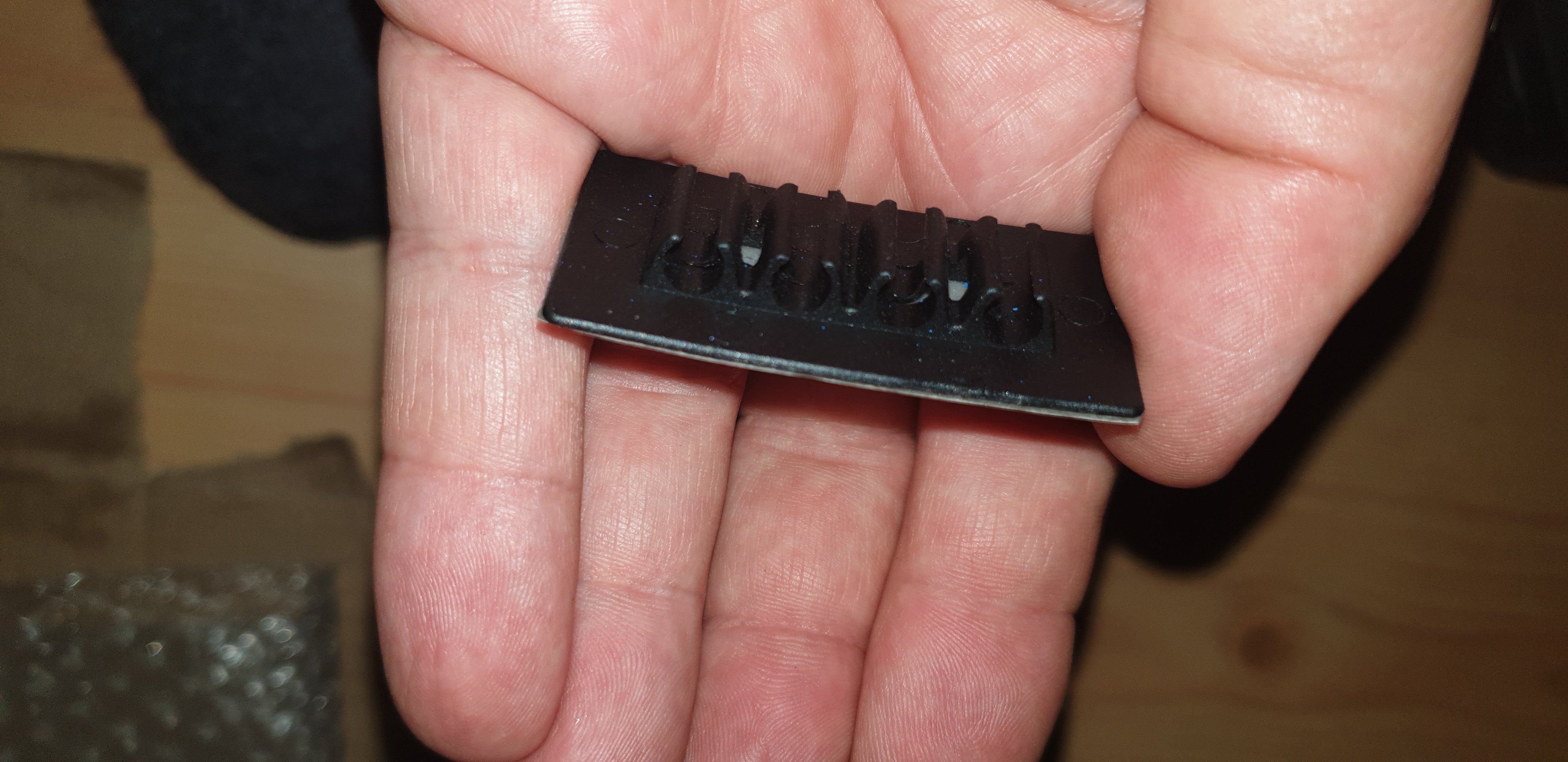
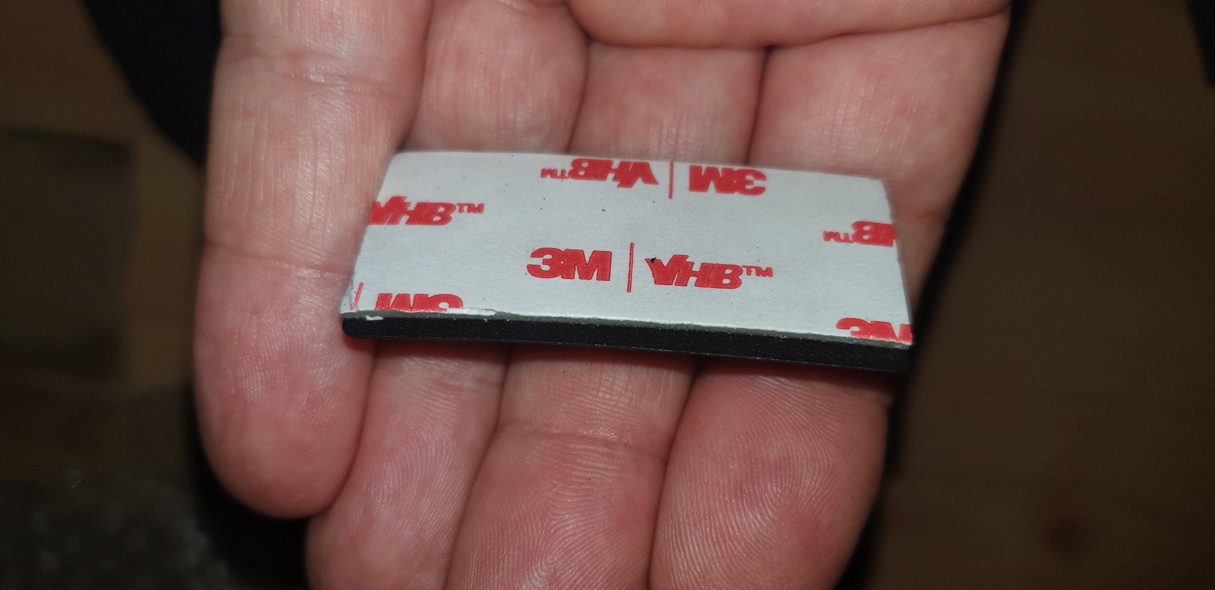
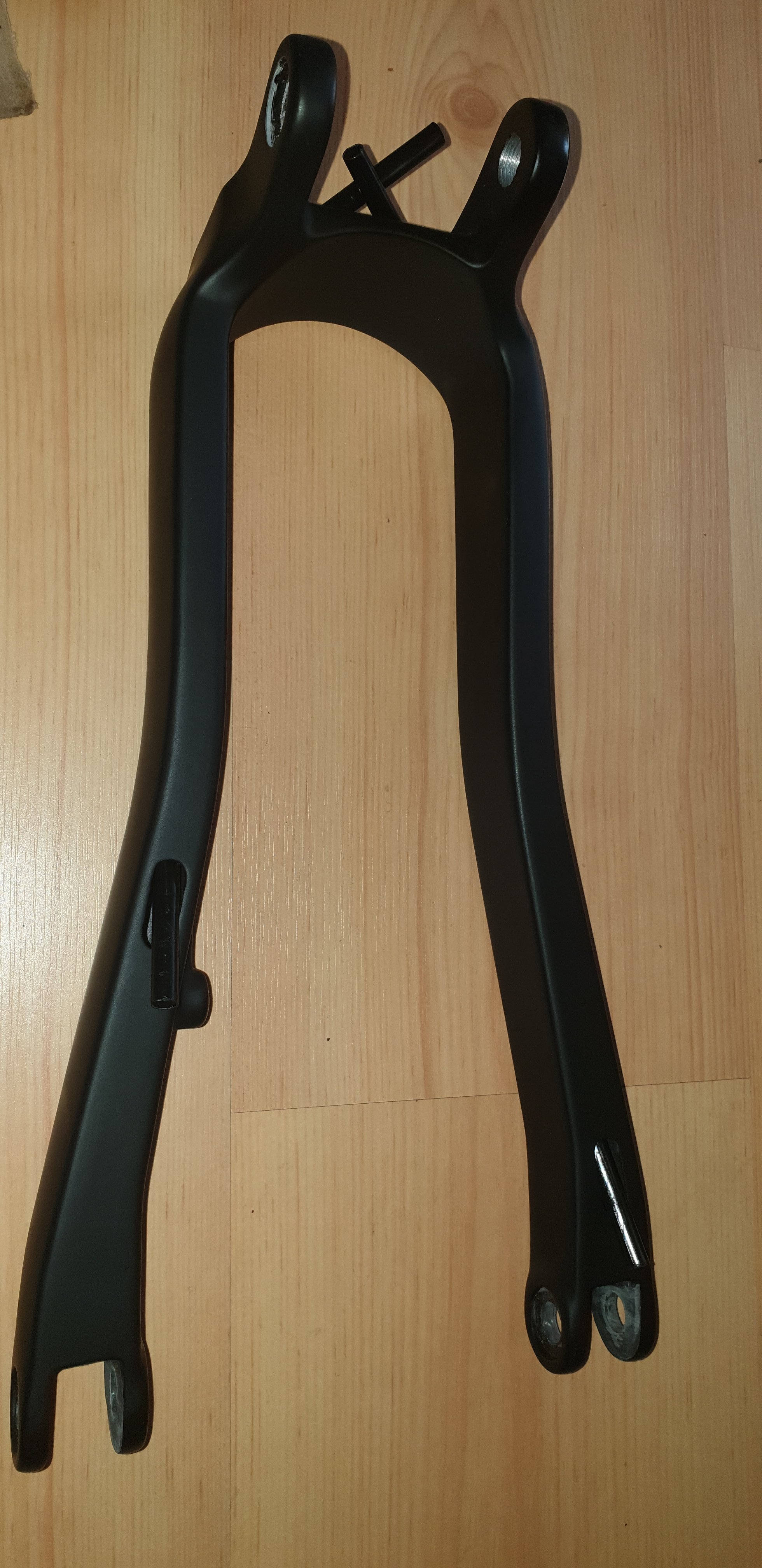
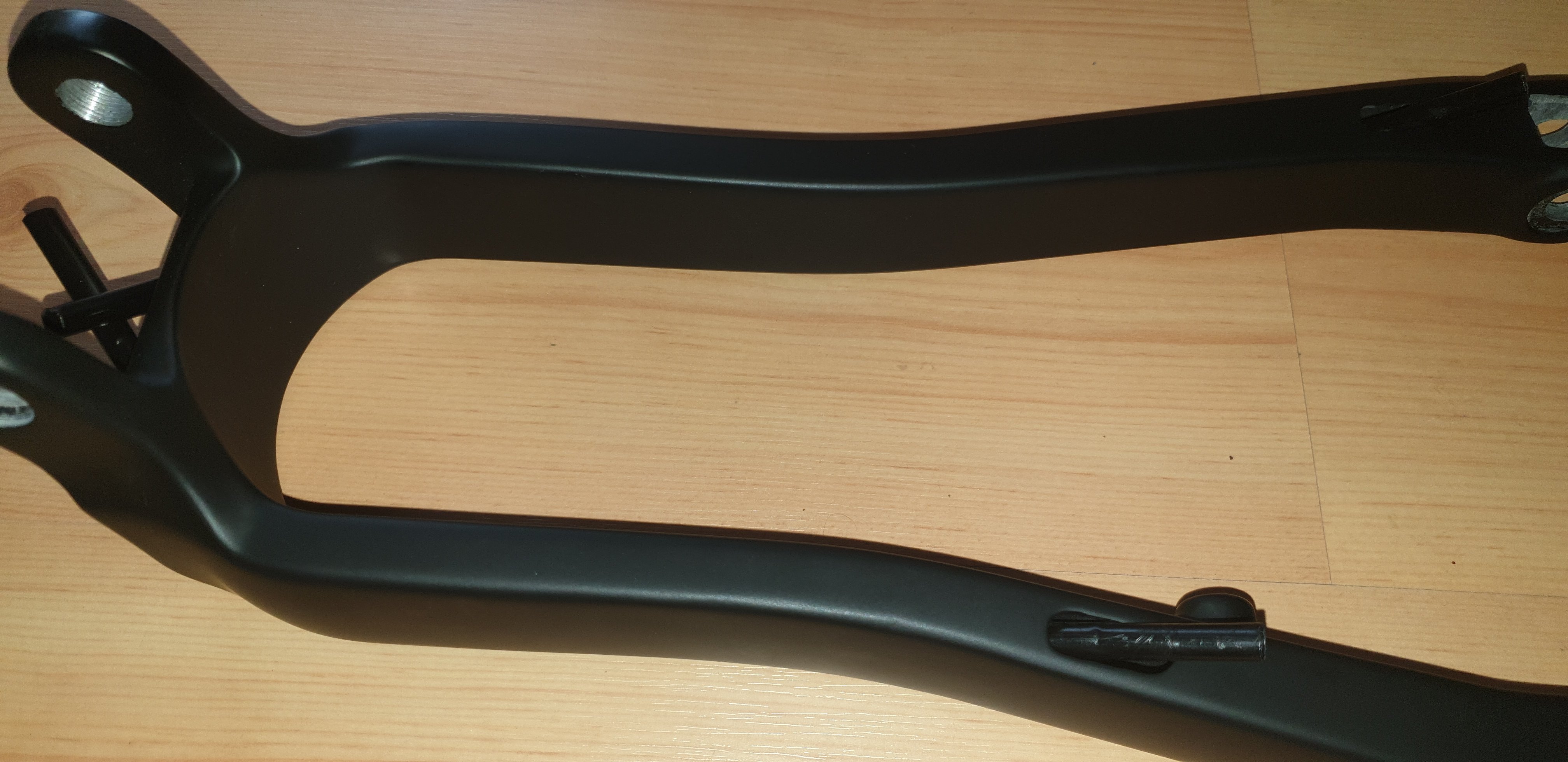


- Thread starter
- #134
I did not have such problem with the washers with the o-rings in those spots. Those washers were hard to stick into the pockets though because of the snug fit of the o-ring, but they were aligned pretty good.
It looks like they removed the ribs at the upper mount of the battery. I'm not sure why. Maybe because of it can interfere with the cables. But I was able to manage the cables around those ribs. Those ribs support the upper battery mount bracket. But maybe the frame has enough stiffness and strength to hold the bracket without the ribs.
I prefer the aluminum cables mounts because of those mounts allow to manage multiple different diameter cables and you can put more cables there (maybe up to 6 cables) while the plastic cable clip is limited by 4 cables and the diameter is fixed which may become an obsticale in cable management.
@BojanZ is this a normal occurrence for E22?Does the rear bend (rear forks/triangle) a little bit when using full power? I have E22 frame and it is noticable on asphalt..
- Thread starter
- #140
I mostly ride it in the rain too and I did not notice any problems with the water. There are not too much water can get in that opening with the rain and if any it should escape through the lower part of the headset (there is a gap on the race crown and the fork) and through the frame openings without touching something water sensitive.
Any water on the cables will be dropping on the lowest part of the cables in the headset area (the cables make like a drip loop in the headset area inside the frame, they go down, then they go up, then they go down in the motor area) so the part of the water which glides on the cables should escape the frame without touching something sensitive too.
Any water on the cables will be dropping on the lowest part of the cables in the headset area (the cables make like a drip loop in the headset area inside the frame, they go down, then they go up, then they go down in the motor area) so the part of the water which glides on the cables should escape the frame without touching something sensitive too.
Last edited:
Dado
Active member
TQ, I do like your skills! Try to estimate how many man hours did this all took to build. Dont include posting photo and writing comments here.
El Topo
Member
Amazing effort, and amazing documentation of it! There is so much to learn for every build.
Thank you.
I think you mentioned these 5800mah cells somewhere, any reason you didn't build a battery with them? Their scarce availability seems suspicious.
Thank you.
I think you mentioned these 5800mah cells somewhere, any reason you didn't build a battery with them? Their scarce availability seems suspicious.
El Topo
Member
Ok, then I must have had something mixed up.I did not mention about 5800mah cells. I was planning to build bigger battery with 21700 cells but I ended up using the stock battery case because of it is very convenient.
Why does nobody use these cells for custom batteries? On paper they look great, but I see them hardly mentioned anywhere. A Google search has very few hits...
Last edited:
- Thread starter
- #147
If you are talking about this cell INR21700-M58T I did not know such thing exists. It was not even in the list of the battery cells where I purchased the cells. But it if it has capacity 5800mAh then you can make 1206Wh battery out of those using the stock case.
You could also go with the Vapcell F60 (rewrapped FEB 21700) https://www.vapcelltech.com/h-pd-202.html for even slightly more capacity. I wouldn't recommend it though for a innotrace motor, but stock they would easily handle that dischargeIf you are talking about this cell INR21700-M58T I did not know such thing exists. It was not even in the list of the battery cells where I purchased the cells. But it if it has capacity 5800mAh then you can make 1206Wh battery out of those using the stock case.
TQFreak I'm stunned at not only the quality of your build but your personal skill and documentation is incredible!!
Now that you have completed the bike can you share more about what the ride /suspension/handling is like and would you still pick the same frame built if you had to do it again?
Thanks
Now that you have completed the bike can you share more about what the ride /suspension/handling is like and would you still pick the same frame built if you had to do it again?
Thanks
- Thread starter
- #150
I would pick the same frame again because of this is the only frame offers such big battery, big motor and looks very good at the same time.
By the way I did not mentioned here but you have to apply Loctite SF7471 primer and Loctite thread locker (probably red is more suitable) on the rear triangle fasteners because of those come loose without thread locker and mark them whit nail polish and keep an eye on them.
I do not have issues with suspension and handling.
Similar threads
EMTB Forums
Since 2018
Join Our Community
The World's largest electric mountain bike community.
- 555K
- Messages
- 28,072
- Members
Latest articles
-
A new standard for charging ebikes is coming? A quick interview with Bosch - charge2bike
I had a quick chat with dr Vikram Godbole about "charge2bike", a new...- Knut Nes
- 2 min read
- Views: 371
- Reaction score: 6
- Comments: 1
-
Introducing the Forestal e-Cygnus - a downcountry and XC emtb
The new Forestal e-Cygnus is a slightly unusual emtb. It comes in two...
