Great! Looking forward to it. Btw did you use a 3rd party reed switch or can I use the smart sensor from Bosch? I already got that, because I was thinking of use the normal speedsensor instead of the rim version and then a tuning device. But yours is way more simple like you've sad. The magnet in your brakedisc, you've glued that? Or just snapped on like a magnet ;-) Anyway, keep on the good work. Looking forward to your tutorial incl the power cable from the aux output. Cheers. SanderI expect to receive the auxiliary power cable in the next couple of days. I'll put something together when it turns up!
-
Warning!!
Riding a tuned or deristricted EMTB is not a trivial offence and can have serious legal consequences. Also, many manufacturers can detect the use of a tuning device or deristricting method and may decline a repair under warranty if it was modified from the intended original specification. Deristricting EMTB's can also add increased loads for motors and batteries. Riding above the local law limit may reclassify the bike as a low-powered bike, requiring insurance, registration and a number plate.
Be aware of your local country laws. Many laws prohibit use of modified EMTB's. It is your responsibility to check local laws. Ignoring it, has potential implications to trail access, and risk of prosecution in the event of an accident.
We advise members great caution. EMTB Forums accepts no liability for any content or advice given here.
You are using an out of date browser. It may not display this or other websites correctly.
You should upgrade or use an alternative browser.
You should upgrade or use an alternative browser.
Derestricting bosch smart system
- Thread starter hallohallo
- Start date
Great! Looking forward to it. Btw did you use a 3rd party reed switch or can I use the smart sensor from Bosch? I already got that, because I was thinking of use the normal speedsensor instead of the rim version and then a tuning device. But yours is way more simple like you've sad. The magnet in your brakedisc, you've glued that? Or just snapped on like a magnet ;-) Anyway, keep on the good work. Looking forward to your tutorial incl the power cable from the aux output. Cheers. Sander
Thanks Sander.
I'm not using Bosch's speed sensor, it's just a random waterproof reed switch
And yep exactly right, the magnet on the disc is just sitting there with... magnets!
SwampNut
Well-known member
Assuming an average 10 MPH speed, and a typical cheap reed switch, that will only last about 8,273 hours of riding. I had to do the math. LOL
But I guess the Bosch speed sensor should also work right? The only thing that wonders me is that Bosch recommends different magnets with different type of speedsensors. Smart slim sensor must have smart magnet. Something with the strength of the magnet? Or a sellingpoint?Thanks Sander.
I'm not using Bosch's speed sensor, it's just a random waterproof reed switch
And yep exactly right, the magnet on the disc is just sitting there with... magnets!
I'm not using Bosch's speed sensor, it's just a random waterproof reed switch
And yep exactly right, the magnet on the disc is just sitting there with... magnets!
The sensor of my first Emtb broke off, and instead of staying put for 8 weeks till the new one arrives, I ducttape-mounted an Aliexpress reed switch that I had for my home alarm.
Worked without issues, after 2K km I removed it, only because the ducttape became loose.
Yes I'm sure the bosch sensor will work, but you'll probably wince a bit when you need to cut the plug off it in order to solder to the arduino!But I guess the Bosch speed sensor should also work right? The only thing that wonders me is that Bosch recommends different magnets with different type of speedsensors. Smart slim sensor must have smart magnet. Something with the strength of the magnet? Or a sellingpoint?
Having said that, it looks like the sensor in the motor which reads the rim magnet is not just a reed switch. Instead it seems to have a built in gauss meter to measure the magnetic field as the rim magnet passes. You can quickly show this by taking your rim magnet and putting it up against the motor - the app will immediately show a 'magnetic field too strong - check magnet' error!
I spent a bit of time measuring the strength of the existing rim magnet at the distance it would be from the motor in order to replicate the strength of the field produced by the electromagnet when it's right next to the motor case.
PS my aux power cable arrived. All wired up an working now from the main battery, powers on and off with the bike too. I'll look to put together a quick guide over the weekend for anyone who wants to give it a go.
My Bosch Gen4 BES3 Smart has the sensor and magnet close/in to the rear brake.... like the sensor in the motor which reads the rim magnet
... taking your rim magnet and putting it up against the motor
... rim magnet at the distance it would be from the motor
... the electromagnet when it's right next to the motor case.
Yours is the Gen4 BES3 Smart "Rim magnet system"
But I didn't expect it to have the sensor IN the motor.
How is that setup done?
Is the sensor bolted directly to the motor casing or really inside the motor casing?
I expected yours to have the sensor mounted on the lower Chain Stay bar opposite side of the chain.
Last edited:
Hooray!!! Cool.Yes I'm sure the bosch sensor will work, but you'll probably wince a bit when you need to cut the plug off it in order to solder to the arduino!
Having said that, it looks like the sensor in the motor which reads the rim magnet is not just a reed switch. Instead it seems to have a built in gauss meter to measure the magnetic field as the rim magnet passes. You can quickly show this by taking your rim magnet and putting it up against the motor - the app will immediately show a 'magnetic field too strong - check magnet' error!
I spent a bit of time measuring the strength of the existing rim magnet at the distance it would be from the motor in order to replicate the strength of the field produced by the electromagnet when it's right next to the motor case.
PS my aux power cable arrived. All wired up an working now from the main battery, powers on and off with the bike too. I'll look to put together a quick guide over the weekend for anyone who wants to give it a go.
The bike manufacture decides if you're riding with a rim magnet or spoke/discbrake magnet. In your case, tuning is easy. A tuning device between your "outside" sensor and input leftside Bosch motor. Even with the smart Bosch motor. But in my and Megabobra's case, the speedsensor is inside the motor, in de backside. Once you ride with rimmagnet (smart system) the firmware cannot be changed. I went to a Bosch dealer to open de "outside" port for a slim speed sensor, but you cannot do that. So the only solution is like the cool device from Megbobra. You'll fool the inside sensor of the motor with a programmable electro magnet.My Bosch Gen4 Smart has the sensor and magnet close/in to the rear brake.
Yours is the Gen4 Smart "Rim magnet system"
But I didn't expect it to have the sensor IN the motor.
How is that setup done?
I expected yours to have the sensor mounted on the lower Chain Stay bar opposite side of the chain.
So the strength/force of the electromagnet cannot be to strong ;-) Smallest around 3 kg?Yes I'm sure the bosch sensor will work, but you'll probably wince a bit when you need to cut the plug off it in order to solder to the arduino!
Having said that, it looks like the sensor in the motor which reads the rim magnet is not just a reed switch. Instead it seems to have a built in gauss meter to measure the magnetic field as the rim magnet passes. You can quickly show this by taking your rim magnet and putting it up against the motor - the app will immediately show a 'magnetic field too strong - check magnet' error!
I spent a bit of time measuring the strength of the existing rim magnet at the distance it would be from the motor in order to replicate the strength of the field produced by the electromagnet when it's right next to the motor case.
PS my aux power cable arrived. All wired up an working now from the main battery, powers on and off with the bike too. I'll look to put together a quick guide over the weekend for anyone who wants to give it a go.
Same as the normal tuning devices ;-)So the sensor is really inside the motor.
Good to see you have a possibility now.
The advantage is that you have some amount of freedom, where to install your magnet emulator.
You've got also a sensor inside, but your bike manufacture decides to use the external sensor. But once decided, Bosch programs the firmware in or out. So you cannot change that afterwards.......So the sensor is really inside the motor.
Good to see you have a possibility now.
The advantage is that you have some amount of freedom, where to install your magnet emulator.
Please refer to the source of that information.You've got also a sensor inside, but .......
Apologies for the repost of some of this, but this single post can be a single point of reference for the rim magnet derestrict.
My build is based on an Ardunio microcontroller, reed switch and electromagnet. I removed the bike's rim magnet and instead placed a traditional magnet on the disc rotor. The Arduino then uses the reed switch to sense the true RPM of the wheel, delays the time between magnet passes by a fixed multiplier and then activates the electromagnet at the new interval accordingly. The electromagnet is positioned up against the motor case.
With ~100 lines of code, everything is working great. I've got the multiplier set to 1.4 (eg where true speed is 20kph, motor will be shown 20/1.4= 14.3kph), giving a new max assisted speed of 35kph. The multiplier could be set to anything, say 2 would give assist to 50kph.
The beauty of this setup is the simplicity: no interruption of sensors from the motor, reducing chance of detection. So long as you don't go crazy with the multiplier, it'd be very difficult for the motor to detect this manipulation, as there are so many real-world variables which will mask it; rider weight, gear ratio, terrain etc. Some things may give it away though. For example, if you use a large multiplier, you may reach a point where for a given cadence it's just not physically possible to be traveling so slowly. Also if you use location tracking through the Eplus app, it may compare wheel speed with GPS speed and flag a discrepancy.
Some FAQ:
Here's a quick tutorial so you can build your own derestrictor for the smart system with rim magnet.
Components:
Wiring Schematic:
Reed switch: D8 and Ground
Transistor: Base > D3, emitter > electromagnet, collector > Ground
Electromagnet: 5v and transistor's collector leg
Voltage regulator: 5v and Ground

The Arduino nano has a built in regulator, so you can also wire the ~13v from the Bosch low power port direct to the Vin and Ground pins in order to omit the voltage regulator above. I had a spare regulator so figured I'd use it to monitor temperatures.
Note that you'll need your Bosch dealer to enable to the low power port before it will be powered.
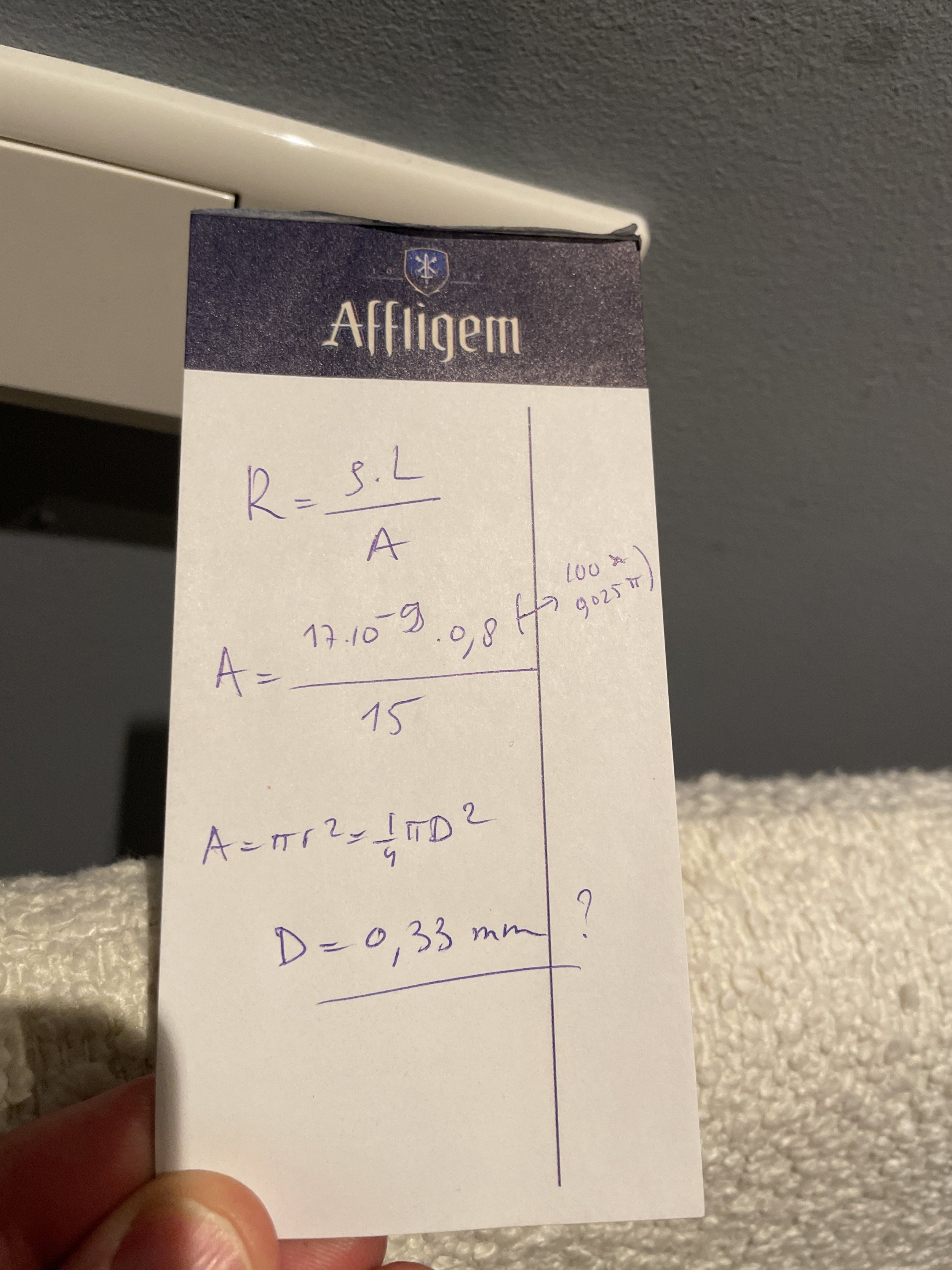
I was also able to build my own electromagnet with some enameled copper wire. You need a coil resistance of ~15ohms. I used 100 turns around some pvc pipe ~ 25mm in diameter and a 0.5watt 10ohm resistor.

These work just as well as the commercial electromagnet and offer better flexibility of placement. If i was starting from scratch, it'd use this rather than the off the shelf product.
Programming
Load the attached code to the Arduino Nano with Arduino IDE. You can download it here.
You can update the Multiplier variable in the code (line 26) to alter the maximum assistance speed. I've got mine set to 1.4. This slows the actual wheel rpm by a factor of 1.4, moving the maximum assistance speed from 25kph to 35kph.
Installation
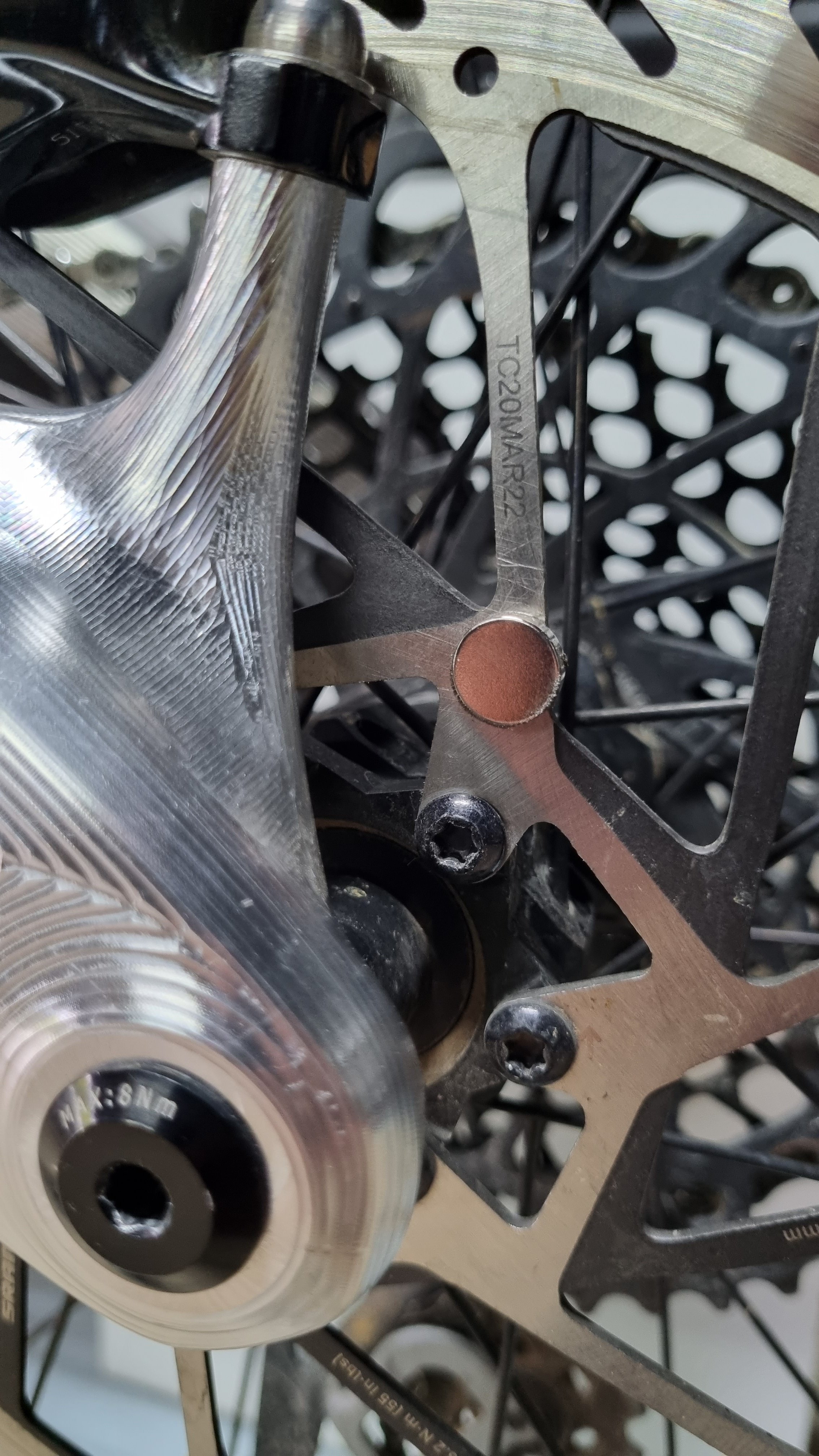
Snap the magnet on to the rear disc rotor. Mount the magnetic switch on the swing arm so that it's close to the rotating magnet.
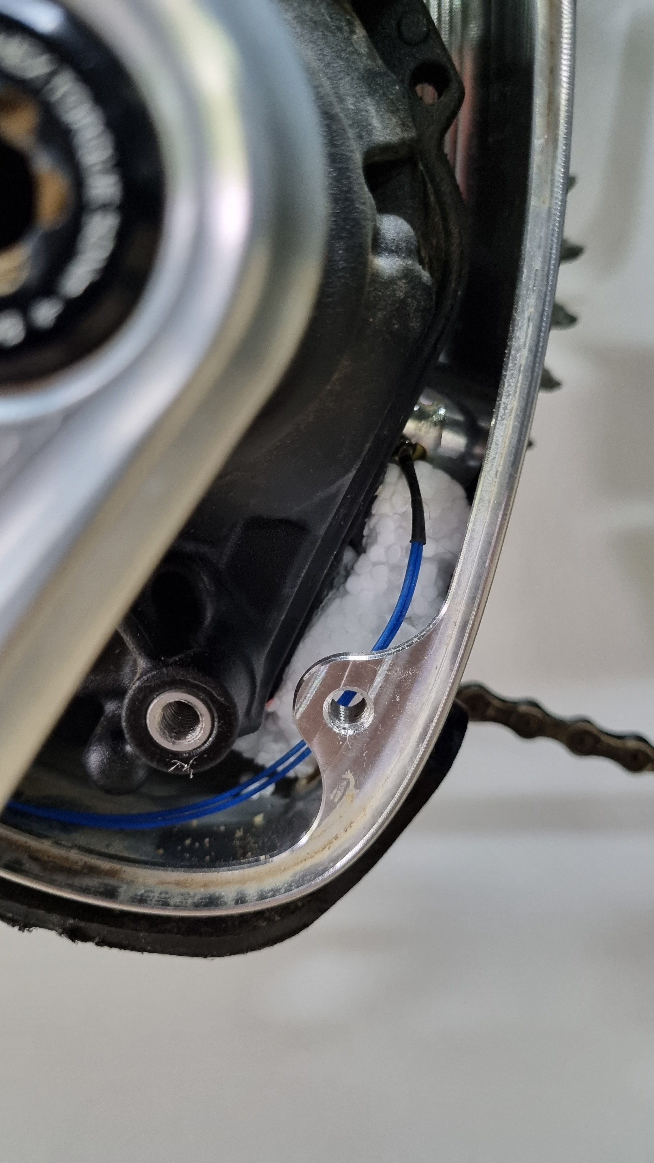
The placement of the electromagnet is a bit tricky as the motor measures the strength of the magnet field, not just if a field exists. I found it best to mount the magnet facing AWAY from the motor (ie magnetic face towards the rear of the bike). Refer to the pics attached for my placement location. I'm using some foam to wedge it in place.
Once wired, the Arduino Nano and all wiring gets pushed into the frame.
Good luck and let me know if there are any questions.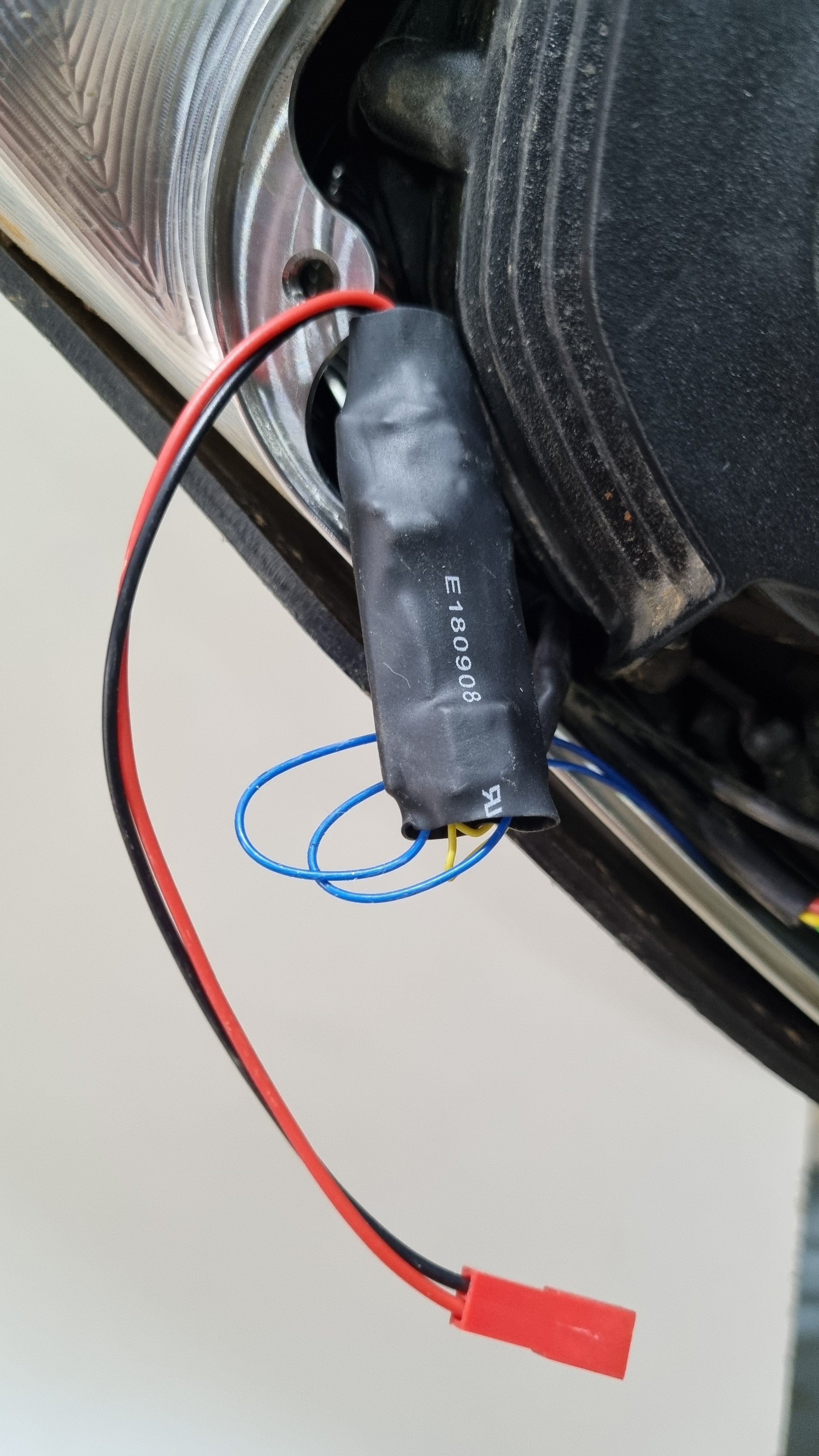
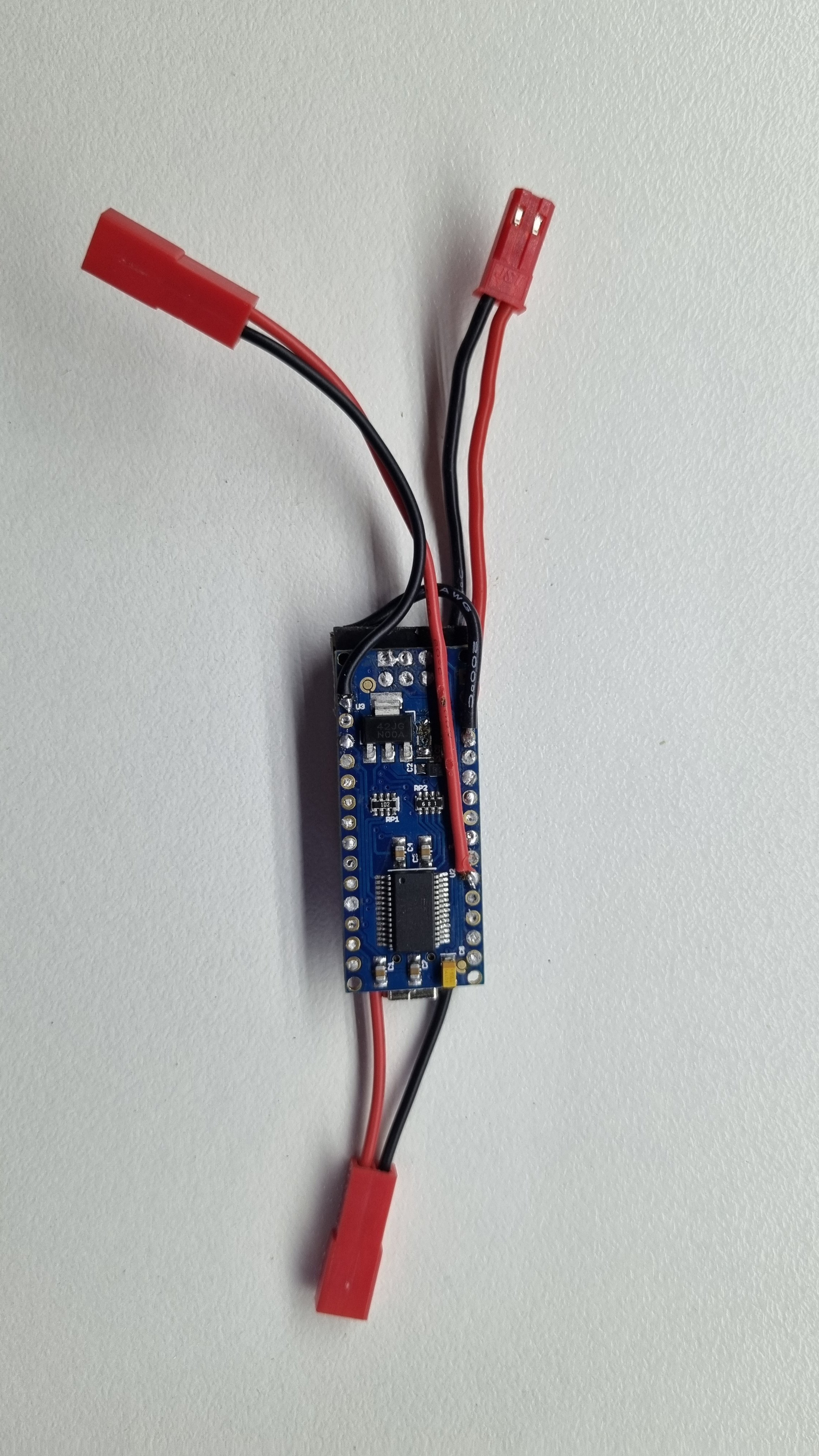
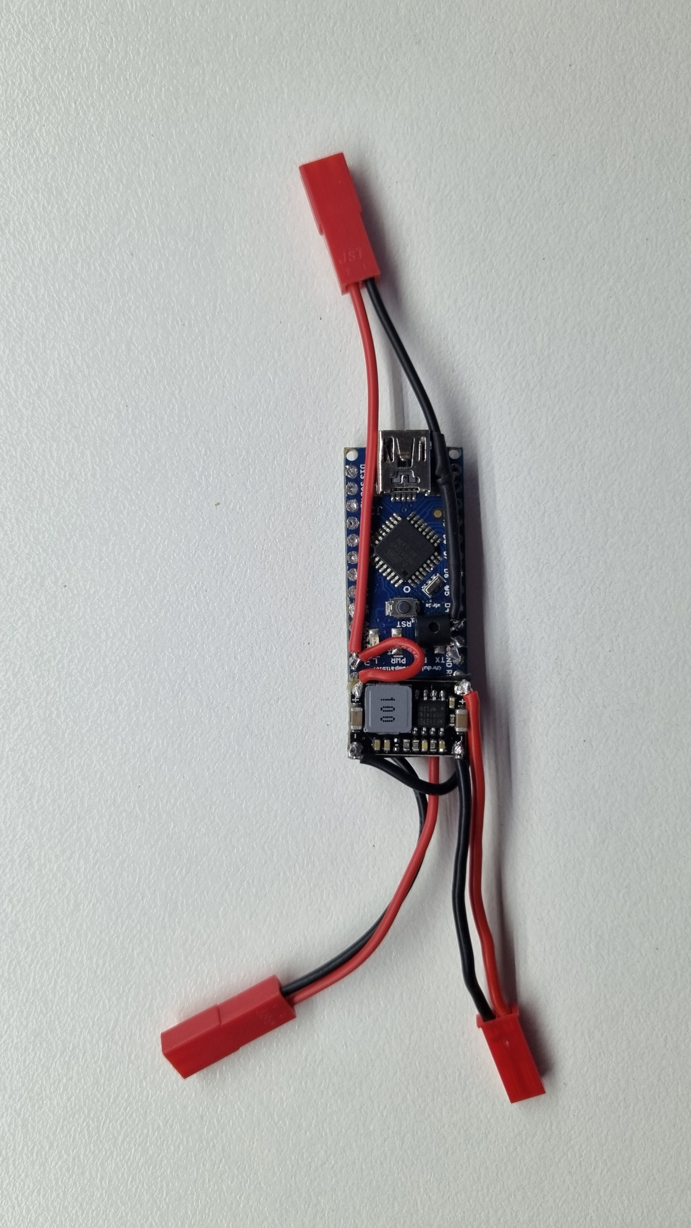
My build is based on an Ardunio microcontroller, reed switch and electromagnet. I removed the bike's rim magnet and instead placed a traditional magnet on the disc rotor. The Arduino then uses the reed switch to sense the true RPM of the wheel, delays the time between magnet passes by a fixed multiplier and then activates the electromagnet at the new interval accordingly. The electromagnet is positioned up against the motor case.
With ~100 lines of code, everything is working great. I've got the multiplier set to 1.4 (eg where true speed is 20kph, motor will be shown 20/1.4= 14.3kph), giving a new max assisted speed of 35kph. The multiplier could be set to anything, say 2 would give assist to 50kph.
The beauty of this setup is the simplicity: no interruption of sensors from the motor, reducing chance of detection. So long as you don't go crazy with the multiplier, it'd be very difficult for the motor to detect this manipulation, as there are so many real-world variables which will mask it; rider weight, gear ratio, terrain etc. Some things may give it away though. For example, if you use a large multiplier, you may reach a point where for a given cadence it's just not physically possible to be traveling so slowly. Also if you use location tracking through the Eplus app, it may compare wheel speed with GPS speed and flag a discrepancy.
Some FAQ:
- YES it will disrupt your total trip distance and odometer, but it's a simple multiplication to get the true figures. ie reported trip distance * chosen multiplier = true trip distance.
- YES it should work on setups without the rim sensor. Instead of positioning the elctromagnet against the motor case, position it against the speed sensor.
- Total power usage when the magnet is firing is ~2.4watts, and negligable when it's not firing (ie when the bike is stationary). Magnet is firing only around 8% of the time.
Here's a quick tutorial so you can build your own derestrictor for the smart system with rim magnet.
Components:
- Arduino Nano
- 5v Electromagnet
- Magnetic contact switch
- 2N2222A transistor
- Switching voltage regulator
- Brake rotor magnet
Wiring Schematic:
Reed switch: D8 and Ground
Transistor: Base > D3, emitter > electromagnet, collector > Ground
Electromagnet: 5v and transistor's collector leg
Voltage regulator: 5v and Ground
The Arduino nano has a built in regulator, so you can also wire the ~13v from the Bosch low power port direct to the Vin and Ground pins in order to omit the voltage regulator above. I had a spare regulator so figured I'd use it to monitor temperatures.
Note that you'll need your Bosch dealer to enable to the low power port before it will be powered.
I was also able to build my own electromagnet with some enameled copper wire. You need a coil resistance of ~15ohms. I used 100 turns around some pvc pipe ~ 25mm in diameter and a 0.5watt 10ohm resistor.
These work just as well as the commercial electromagnet and offer better flexibility of placement. If i was starting from scratch, it'd use this rather than the off the shelf product.
Programming
Load the attached code to the Arduino Nano with Arduino IDE. You can download it here.
You can update the Multiplier variable in the code (line 26) to alter the maximum assistance speed. I've got mine set to 1.4. This slows the actual wheel rpm by a factor of 1.4, moving the maximum assistance speed from 25kph to 35kph.
Installation
Snap the magnet on to the rear disc rotor. Mount the magnetic switch on the swing arm so that it's close to the rotating magnet.
The placement of the electromagnet is a bit tricky as the motor measures the strength of the magnet field, not just if a field exists. I found it best to mount the magnet facing AWAY from the motor (ie magnetic face towards the rear of the bike). Refer to the pics attached for my placement location. I'm using some foam to wedge it in place.
Once wired, the Arduino Nano and all wiring gets pushed into the frame.
Good luck and let me know if there are any questions.


Attachments
Last edited:
Great! Thx for the tutorial Megabobra. The output of the battery is 12v and if I find a electromagnet of 12v (which there is) there's no need of a voltageregulator right? Like you've said one less component.Apologies for the repost of some of this, but this single post can be a single point of reference for the rim magnet derestrict.
My build is based on an Ardunio microcontroller, reed switch and electromagnet. I removed the bike's rim magnet and instead placed a traditional magnet on the disc rotor. The Arduino then uses the reed switch to sense the true RPM of the wheel, delays the time between magnet passes by a fixed multiplier and then activates the electromagnet at the new interval accordingly. The electromagnet is positioned up against the motor case.
With ~100 lines of code, everything is working great. I've got the multiplier set to 1.4 (eg where true speed is 20kph, motor will be shown 20/1.4= 14.3kph), giving a new max assisted speed of 35kph. The multiplier could be set to anything, say 2 would give assist to 50kph.
The beauty of this setup is the simplicity: no interruption of sensors from the motor, reducing chance of detection. So long as you don't go crazy with the multiplier, it'd be very difficult for the motor to detect this manipulation, as there are so many real-world variables which will mask it; rider weight, gear ratio, terrain etc. Some things may give it away though. For example, if you use a large multiplier, you may reach a point where for a given cadence it's just not physically possible to be traveling so slowly. Also if you use location tracking through the Eplus app, it may compare wheel speed with GPS speed and flag a discrepancy.
Some FAQ:
- YES it will disrupt your total trip distance and odometer, but it's a simple multiplication to get the true figures. ie reported trip distance * chosen multiplier = true trip distance.
- YES it should work on setups without the rim sensor. Instead of positioning the elctromagnet against the motor case, position it against the speed sensor.
- Total power usage when the magnet is firing is ~2.4watts, and negligable when it's not firing (ie when the bike is stationary). Magnet is firing only around 8% of the time.
Here's a quick tutorial so you can build your own derestrictor for the smart system with rim magnet.
Components:
Of course there's plenty of equivalent components you can substitute here, so go with what's cheap/easy to get locally.
- Arduino Nano
- 5v Electromagnet
- Magnetic contact switch
- 2N2222A transistor
- Switching voltage regulator
- Rim magnet
Wiring Schematic:
Reed switch: D8 and Ground
Transistor: Base > Ground, collector > electromagnet, emitter > D3
Electromagnet: 5v and transistor's collector leg
Voltage regulator: 5v and Ground
View attachment 105957
The Arduino nano has a built in regulator, so you can also wire the ~13v from the Bosch low power port direct to the Vin and Ground pins in order to omit the voltage regulator above. I had a spare regulator so figured I'd use it to monitor temperatures.
Note that you'll need your Bosch dealer to enable to the low power port before it will be powered.
I was also able to build my own electromagnet with some enameled copper wire. You need a coil resistance of ~15ohms. I used 100 turns around some pvc pipe ~ 25mm in diameter and a 0.5watt 10ohm resistor.
View attachment 105975
These work just as well as the commercial electromagnet and offer better flexibility of placement. If i was starting from scratch, it'd use this rather than the off the shelf product.
Programming
Load the attached code to the Arduino Nano with Arduino IDE. You can download it here.
You can update the Multiplier variable in the code (line 26) to alter the maximum assistance speed. I've got mine set to 1.4. This slows the actual wheel rpm by a factor of 1.4, moving the maximum assistance speed from 25kph to 35kph.
Installation
Snap the magnet on to the rear disc rotor. Mount the magnetic switch on the swing arm so that it's close to the rotating magnet.
The placement of the electromagnet is a bit tricky as the motor measures the strength of the magnet field, not just if a field exists. I found it best to mount the magnet facing AWAY from the motor (ie magnetic face towards the rear of the bike). Refer to the pics attached for my placement location. I'm using some foam to wedge it in place.
Once wired, the Arduino Nano and all wiring gets pushed into the frame.
Good luck and let me know if there are any questions. View attachment 105963 View attachment 105964 View attachment 105965 View attachment 105976 View attachment 105977
Great! Thx for the tutorial Megabobra. The output of the battery is 12v and if I find a electromagnet of 12v (which there is) there's no need of a voltageregulator right? Like you've said one less component.
Yep you're right, but you'll probably just need to add a resistor to reduce the increased magnetic strength of the electromagnet (due to the extra voltage). It's easy to do if you need it; resistors are just added in line to the magnet. You'd probably need something like 10-20ohm resistor, depending on the internal resistance of the magnet.
So input battery on Vin and GR, like wise 12V electromagnet? Including resistor.Yep you're right, but you'll probably just need to add a resistor to reduce the increased magnetic strength of the electromagnet (due to the extra voltage). It's easy to do if you need it; resistors are just added in line to the magnet. You'd probably need something like 10-20ohm resistor, depending on the internal resistance of the magnet.
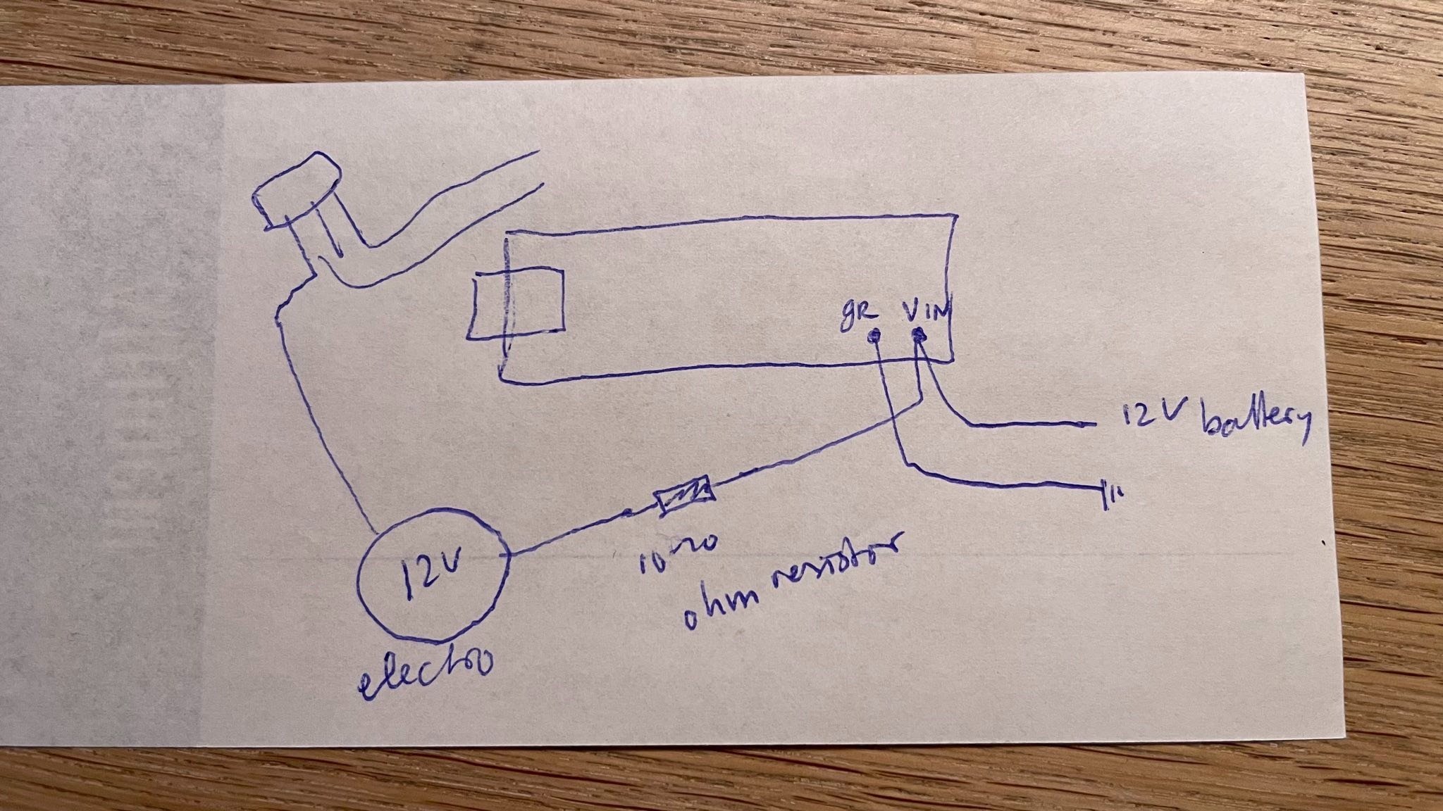
12V electromagnet is around 80 OhmYep you're right, but you'll probably just need to add a resistor to reduce the increased magnetic strength of the electromagnet (due to the extra voltage). It's easy to do if you need it; resistors are just added in line to the magnet. You'd probably need something like 10-20ohm resistor, depending on the internal resistance of the magnet.
12V electromagnet is around 80 Ohm
Yes your wiring is correct. But at 80ohm, you might need a larger resistor:
The 5v magnet is around 15ohms, giving 0.28A current draw = 1.39watts
Your 12v magnet @ 80ohms will draw 0.15A = 1.8watts
To achieve the same wattage, you'd need ~100ohms total, so a 20ohm resistor to be added.
Though I'm just guessing here that a similar wattage will give a similar magnetic field strength!
I suggest just grabbing a few resistors in case you need to experiment in either direction...
For simple calculations of the magnetic flux only the current through the coil is important.
For more advanced calculations the source impedance comes into play.
The voltage over the coil is there as a side effect of the current, and never relevant in flux calculations.
In the example above the 12V setup will generate less magnetic flux.
Barbar
New Member
I'm the 1 new member and stil can tell you that my speedbox works as it should be, now febr 5 and more than 500 km's too.Think I would want more confirmation than 1 new forum member whose total of 5 posts only relate to Speedbox........which according to his own posts he only installed 2 weeks ago.
In my group no complaints at all with the present speed boxes for Bosch smart system.
Greetings from Holland
Hi there,Apologies for the repost of some of this, but this single post can be a single point of reference for the rim magnet derestrict.
My build is based on an Ardunio microcontroller, reed switch and electromagnet. I removed the bike's rim magnet and instead placed a traditional magnet on the disc rotor. The Arduino then uses the reed switch to sense the true RPM of the wheel, delays the time between magnet passes by a fixed multiplier and then activates the electromagnet at the new interval accordingly. The electromagnet is positioned up against the motor case.
With ~100 lines of code, everything is working great. I've got the multiplier set to 1.4 (eg where true speed is 20kph, motor will be shown 20/1.4= 14.3kph), giving a new max assisted speed of 35kph. The multiplier could be set to anything, say 2 would give assist to 50kph.
The beauty of this setup is the simplicity: no interruption of sensors from the motor, reducing chance of detection. So long as you don't go crazy with the multiplier, it'd be very difficult for the motor to detect this manipulation, as there are so many real-world variables which will mask it; rider weight, gear ratio, terrain etc. Some things may give it away though. For example, if you use a large multiplier, you may reach a point where for a given cadence it's just not physically possible to be traveling so slowly. Also if you use location tracking through the Eplus app, it may compare wheel speed with GPS speed and flag a discrepancy.
Some FAQ:
- YES it will disrupt your total trip distance and odometer, but it's a simple multiplication to get the true figures. ie reported trip distance * chosen multiplier = true trip distance.
- YES it should work on setups without the rim sensor. Instead of positioning the elctromagnet against the motor case, position it against the speed sensor.
- Total power usage when the magnet is firing is ~2.4watts, and negligable when it's not firing (ie when the bike is stationary). Magnet is firing only around 8% of the time.
Here's a quick tutorial so you can build your own derestrictor for the smart system with rim magnet.
Components:
Of course there's plenty of equivalent components you can substitute here, so go with what's cheap/easy to get locally.
- Arduino Nano
- 5v Electromagnet
- Magnetic contact switch
- 2N2222A transistor
- Switching voltage regulator
- Rim magnet
Wiring Schematic:
Reed switch: D8 and Ground
Transistor: Base > Ground, collector > electromagnet, emitter > D3
Electromagnet: 5v and transistor's collector leg
Voltage regulator: 5v and Ground
View attachment 105957
The Arduino nano has a built in regulator, so you can also wire the ~13v from the Bosch low power port direct to the Vin and Ground pins in order to omit the voltage regulator above. I had a spare regulator so figured I'd use it to monitor temperatures.
Note that you'll need your Bosch dealer to enable to the low power port before it will be powered.
I was also able to build my own electromagnet with some enameled copper wire. You need a coil resistance of ~15ohms. I used 100 turns around some pvc pipe ~ 25mm in diameter and a 0.5watt 10ohm resistor.
View attachment 105975
These work just as well as the commercial electromagnet and offer better flexibility of placement. If i was starting from scratch, it'd use this rather than the off the shelf product.
Programming
Load the attached code to the Arduino Nano with Arduino IDE. You can download it here.
You can update the Multiplier variable in the code (line 26) to alter the maximum assistance speed. I've got mine set to 1.4. This slows the actual wheel rpm by a factor of 1.4, moving the maximum assistance speed from 25kph to 35kph.
Installation
Snap the magnet on to the rear disc rotor. Mount the magnetic switch on the swing arm so that it's close to the rotating magnet.
The placement of the electromagnet is a bit tricky as the motor measures the strength of the magnet field, not just if a field exists. I found it best to mount the magnet facing AWAY from the motor (ie magnetic face towards the rear of the bike). Refer to the pics attached for my placement location. I'm using some foam to wedge it in place.
Once wired, the Arduino Nano and all wiring gets pushed into the frame.
Good luck and let me know if there are any questions. View attachment 105963 View attachment 105964 View attachment 105965 View attachment 105976 View attachment 105977
I've soldered the parts to the Arduino. Uploaded you code. But no action
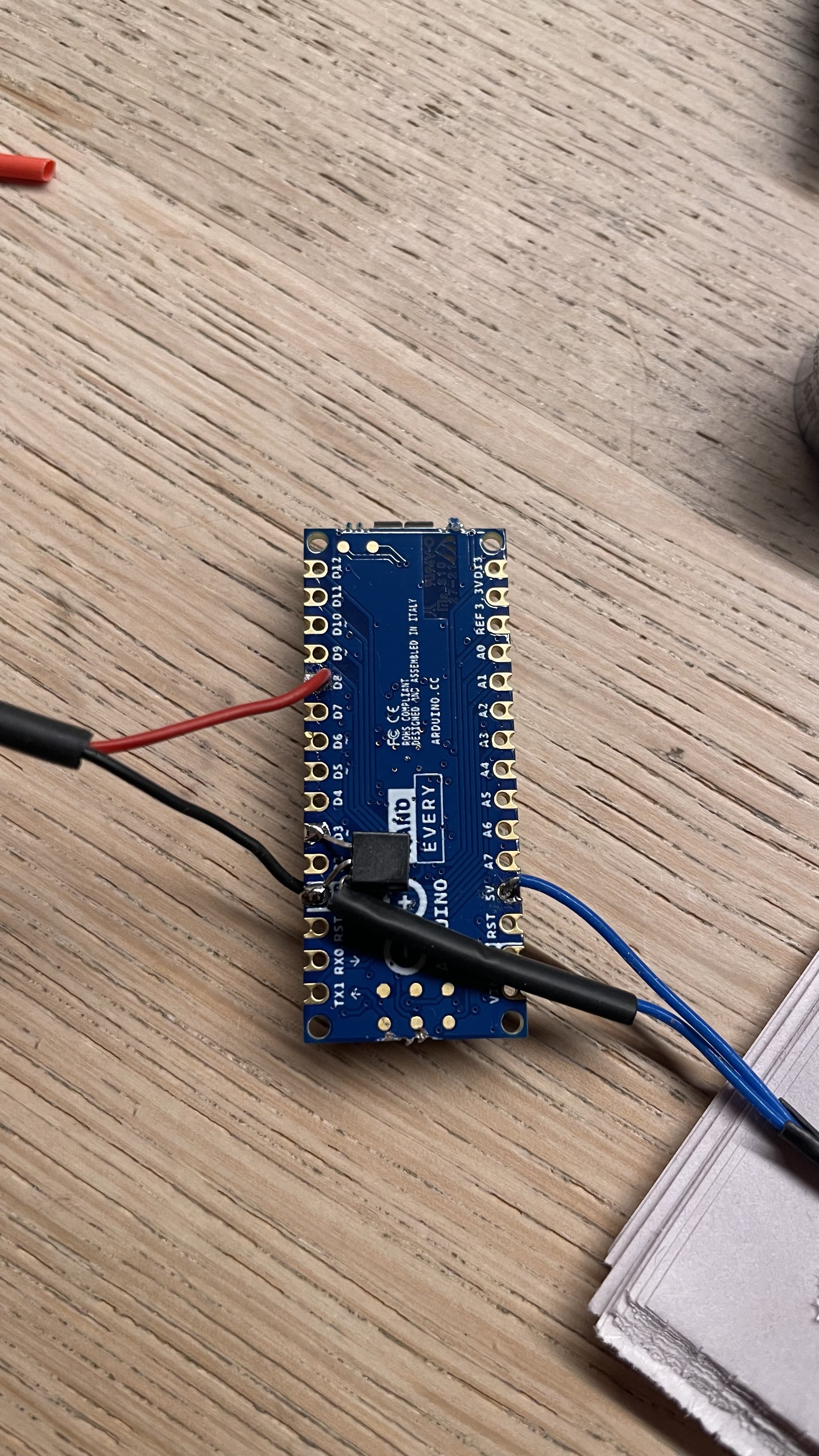
Hi there,
I've soldered the parts to the Arduino. Uploaded you code. But no action. If I pass a magnet aside to the reedswitch, the electro magnet should work right. It should lift up some metal. I use a usb to power the arduino nano every.
View attachment 106399
Hi Sander,
You'll need to power the device externally in order to give enough power to the electromagnet - USB won't deliver enough. Also, did you end up getting the 12v magnet? If so that could also be the trouble when attempting to power it from the 5v output.
Let me know how you go?
First I've got a 5V magnet, so thats ok. Second I wired the Arduino up with your written attachement of the 2n222: base > ground etc. But nothing happened. Then I saw in your figure that the transmitter was attached differently: emitter is magnet, base is pin 3 and collector is ground. And it worked ;-). But the strength of the magnet was weak. Which you explained. To be continued.Hi Sander,
You'll need to power the device externally in order to give enough power to the electromagnet - USB won't deliver enough. Also, did you end up getting the 12v magnet? If so that could also be the trouble when attempting to power it from the 5v output.
Let me know how you go?
First I've got a 5V magnet, so thats ok. Second I wired the Arduino up with your written attachement of the 2n222: base > ground etc. But nothing happened. Then I saw in your figure that the transmitter was attached differently: emitter is magnet, base is pin 3 and collector is ground. And it worked ;-). But the strength of the magnet was weak. Which you explained. To be continued.
Ahh good spotting - I've updated the text above!
Device seems to work now with the lowpower 12v output motor. Now find a way to get magnet between the motor and frame.Ahh good spotting - I've updated the text above!
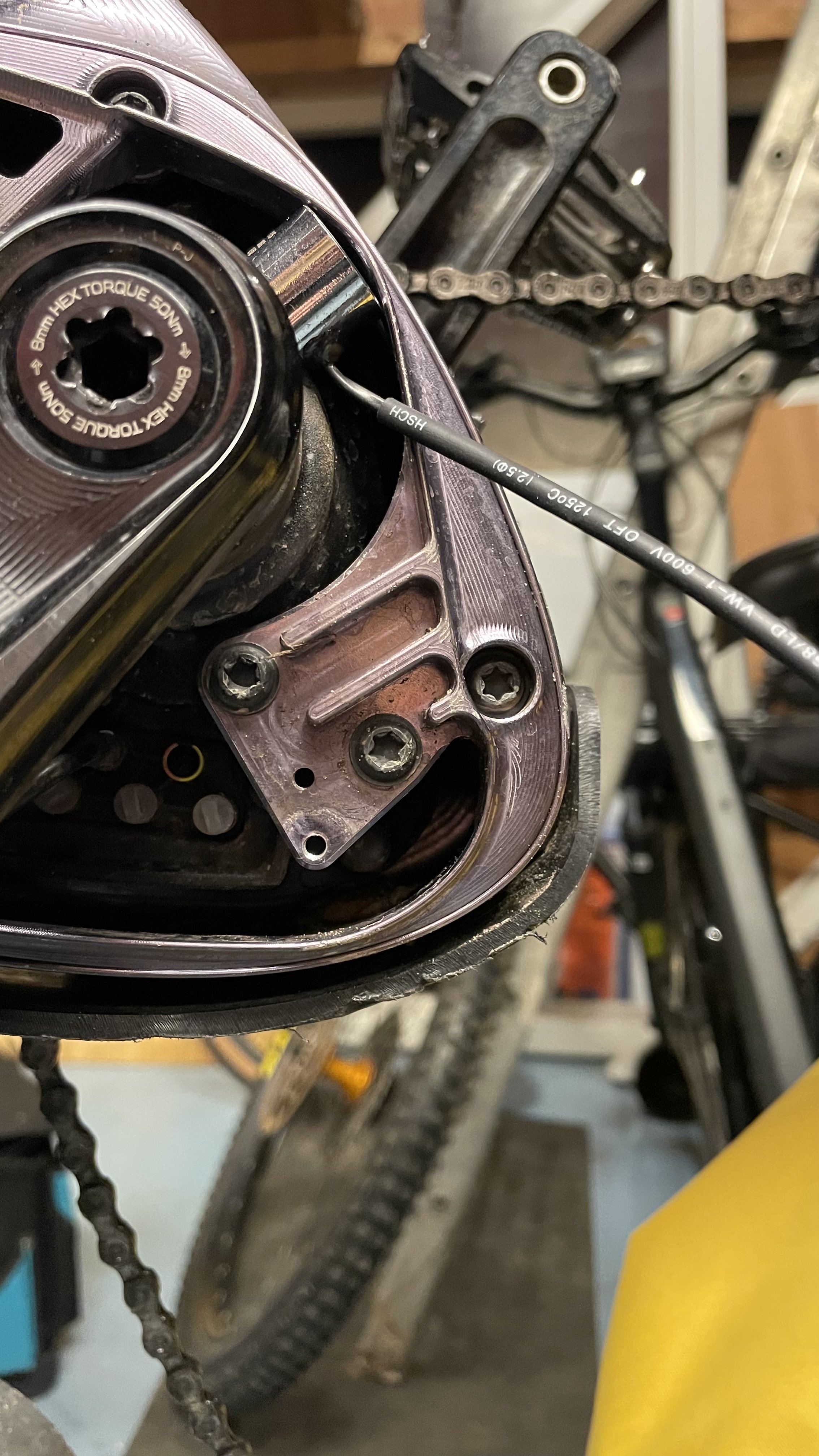
I think I make the electro magnet myself like you did. What is the diameter of the enameled copper wire? And a resistor? I can see it on you pictures of your homemade magnetsHi Sander,
You'll need to power the device externally in order to give enough power to the electromagnet - USB won't deliver enough. Also, did you end up getting the 12v magnet? If so that could also be the trouble when attempting to power it from the 5v output.
Let me know how you go?
Hello guys! I have Mondraker Chaser 2022 with Smart System and Disk magnet. I would like to deristrict it, what would be my best option ?
I'm a bit scared of Speedbox with all the negative reviews. Its really rare to find people riding with it for more than 300kms
I heard about PearTune MSO 4.0 or even the speedfun?
There is also a new device coming in march Splug Dongle.
What would be my best option?
Thanks
I'm a bit scared of Speedbox with all the negative reviews. Its really rare to find people riding with it for more than 300kms
I heard about PearTune MSO 4.0 or even the speedfun?
There is also a new device coming in march Splug Dongle.
What would be my best option?
Thanks
Similar threads
- Replies
- 4
- Views
- 1K
- Replies
- 404
- Views
- 91K
EMTB Forums
Since 2018
Join Our Community
The World's largest electric mountain bike community.
- 577K
- Messages
- 29,368
- Members
