• Warning!!

    Riding a tuned or deristricted EMTB is not a trivial offence and can have serious legal consequences. Also, many manufacturers can detect the use of a tuning device or deristricting method and may decline a repair under warranty if it was modified from the intended original specification. Deristricting EMTB's can also add increased loads for motors and batteries. Riding above the local law limit may reclassify the bike as a low-powered bike, requiring insurance, registration and a number plate.

    Be aware of your local country laws. Many laws prohibit use of modified EMTB's. It is your responsibility to check local laws. Ignoring it, has potential implications to trail access, and risk of prosecution in the event of an accident.

    UK Pedelec Law

    Worldwide Laws

    We advise members great caution. EMTB Forums accepts no liability for any content or advice given here. 


Derestricting bosch smart system

megabobra

Active member
Jul 24, 2022
266
268
Australia
Unfortunately I got 524001 today. This was after 1030 km with the system installed.
@megabobra, how many km did you do with your system/code?

Sorry to hear that Koekie. I'm on ~600km on mine - clearly I don't get out as much as you!!
I wonder if the chatGPT approach with the constant ms signal delay contributed to it?
 

Koekie

Member
May 2, 2023
23
38
Antwerp, Belgium
Sorry to hear that Koekie. I'm on ~600km on mine - clearly I don't get out as much as you!!
I wonder if the chatGPT approach with the constant ms signal delay contributed to it?
I have no idea what the reason is but that detection system of Bosch could be rather advanced. I read some patents from Bosch that talk about that. I have to look that back up.

I would recommend you to try and go over 1000 km before making any devices for other people.

I just did a 10 day trekking in Denmark and some more multi day trips here in Belgium, luckily it didn't stop during those trips.
 

tatane

Member
Jun 25, 2023
59
41
Southern France
Sorry to hear that Koekie. I'm on ~600km on mine - clearly I don't get out as much as you!!
I wonder if the chatGPT approach with the constant ms signal delay contributed to it?
Couple wild guesses at what we (may) learn from that :
- Seems the dreadded 1000km "limit" where the motor does extra checks that gets most of the modchips flagged might be taken from what distance these chips feed the engine ... would a higher multi have caused it to happen later ? (@Koekie mentionned that his 1000km are likely more like 2000 due to his multi)
- Could it be that the higher multi used triggered the protection (basically seeing higher avg speeds or lower avg cadence (as in motor sanity-check not believing you'd spend so much time at 10-12Km/h) ?
- Constant ms being used by other chips, maybe bosch had put some clever algo in place to detect that induced curve ? (changing speeds could very well be factored in by the motor using the torque sensor to detect those, thus also explaining why it wouldn't flag right away but only after having collected enough data to filter those out)
 

Koekie

Member
May 2, 2023
23
38
Antwerp, Belgium
Couple wild guesses at what we (may) learn from that :
- Seems the dreadded 1000km "limit" where the motor does extra checks that gets most of the modchips flagged might be taken from what distance these chips feed the engine ... would a higher multi have caused it to happen later ? (@Koekie mentionned that his 1000km are likely more like 2000 due to his multi)
- Could it be that the higher multi used triggered the protection (basically seeing higher avg speeds or lower avg cadence (as in motor sanity-check not believing you'd spend so much time at 10-12Km/h) ?
- Constant ms being used by other chips, maybe bosch had put some clever algo in place to detect that induced curve ? (changing speeds could very well be factored in by the motor using the torque sensor to detect those, thus also explaining why it wouldn't flag right away but only after having collected enough data to filter those out)
Here a Bosch patent: DE102017212903A1 - Method and device for monitoring the movement of a wheel of a bicycle - Google Patents

Interesting read, not sure if this is implemented.
Uses magnetometers in 3 axis.
 

Koekie

Member
May 2, 2023
23
38
Antwerp, Belgium
Sorry to hear that Koekie. I'm on ~600km on mine - clearly I don't get out as much as you!!
I wonder if the chatGPT approach with the constant ms signal delay contributed to it?
The constant ms signal delay is not an idea from ChatGPT but what I measured (reverse engineered) on a commercial tuning product I had on my previous bike.
 

tatane

Member
Jun 25, 2023
59
41
Southern France
Here a Bosch patent: DE102017212903A1 - Method and device for monitoring the movement of a wheel of a bicycle - Google Patents

Interesting read, not sure if this is implemented.
Uses magnetometers in 3 axis.
from that doc :
The comparison of the magnetic field sensor signals can be made by observing the amplitude, the peak shape, the peak height, the maximum values, the measured value integral (over one revolution or a measured value peak) and the number of peaks within the magnetic field sensor signals. The deviation is usually determined as difference or difference.
seems to me like we may need to up our game and have more precise measurements of that magnetic field/have to reproduce it more precisely to avoid detection
 

megabobra

Active member
Jul 24, 2022
266
268
Australia
I have no idea what the reason is but that detection system of Bosch could be rather advanced. I read some patents from Bosch that talk about that. I have to look that back up.

I would recommend you to try and go over 1000 km before making any devices for other people.

I just did a 10 day trekking in Denmark and some more multi day trips here in Belgium, luckily it didn't stop during those trips.

Very interesting read on the patent. Sadly it'll be some time before I get to the 1000km mark, but yes I completely agree with as much testing as possible is needed . Frankly I'm not in an rush to build devices if there's a risk that they'll behave like this in the longer term. @Sander , I wonder if you might have the greatest number of km on the device now - please keep us informed?
Having said that, I'd say there's always going to be improvements made to the detection routines for these devices, to the point where someday it won't be possible outsmart it. Maybe it's just best to make the most of it while we still can!!

from that doc :

seems to me like we may need to up our game and have more precise measurements of that magnetic field/have to reproduce it more precisely to avoid detection

Yes agree. I wonder how sophisticated the measurement is though, because that patent refers to the profile or ramping up/down of the signal as well. With the electromagnet in place, even with exactly the right strength to mimic the magnetic field, the ramping up and down is going to look very different. Where the passing magnet on the wheel will create a nicely smooth sine wave, the coil will be very much a square-edged step wave.
 

tatane

Member
Jun 25, 2023
59
41
Southern France
Very interesting read on the patent. Sadly it'll be some time before I get to the 1000km mark, but yes I completely agree with as much testing as possible is needed . Frankly I'm not in an rush to build devices if there's a risk that they'll behave like this in the longer term. @Sander , I wonder if you might have the greatest number of km on the device now - please keep us informed?
Having said that, I'd say there's always going to be improvements made to the detection routines for these devices, to the point where someday it won't be possible outsmart it. Maybe it's just best to make the most of it while we still can!!


Yes agree. I wonder how sophisticated the measurement is though, because that patent refers to the profile or ramping up/down of the signal as well. With the electromagnet in place, even with exactly the right strength to mimic the magnetic field, the ramping up and down is going to look very different. Where the passing magnet on the wheel will create a nicely smooth sine wave, the coil will be very much a square-edged step wave.
Couldn't we use the PWM pins on the nano to generate a sine wave ? (please forgive my ignorance, just throwing wild guesses here after reading a couple google results :geek:)
 

megabobra

Active member
Jul 24, 2022
266
268
Australia
Couldn't we use the PWM pins on the nano to generate a sine wave ? (please forgive my ignorance, just throwing wild guesses here after reading a couple google results :geek:)
I think though you'd need something which can pass that regulated power along in more than simply an on-off state. At the moment, the transistor can either be on or off, and while the PWM outputs do allow for an inbetween value, they're not able to power the coil on their own. So essentially you would need a transistor which allows for the output to be controlled proporitionally to the input. Sadly that's beyond my level of electronics expertise!
 

Koekie

Member
May 2, 2023
23
38
Antwerp, Belgium
I think though you'd need something which can pass that regulated power along in more than simply an on-off state. At the moment, the transistor can either be on or off, and while the PWM outputs do allow for an inbetween value, they're not able to power the coil on their own. So essentially you would need a transistor which allows for the output to be controlled proporitionally to the input. Sadly that's beyond my level of electronics expertise!
For sure more advanced things can be done like controlling the output with a varying PWM signal that then simulates a more smoother magnetic field pulse.
But the problem is that you only see after 2000 km if it is detected or not. Furthermore after 3 detections you have to go to a Bosch ebike shop to remove the 524001 error....
 

Koekie

Member
May 2, 2023
23
38
Antwerp, Belgium
Unfortunately I got 524001 today. This was after 1030 km with the system installed. (1030 km as shown on the Bosch display, probably in reality close to 2000 km)
@megabobra, how many km did you do with your system/code?
I double checked my notes, and I got the 524001 error after riding 1145 km with the modification (as measured by the Bosch display).
 

Ashley3283

New Member
Jun 27, 2023
16
4
UK
Unfortunately I got 524001 today. This was after 1030 km with the system installed. (1030 km as shown on the Bosch display, probably in reality close to 2000 km)
@megabobra, how many km did you do with your system/code?
What was you using? Did you have the flow app connected, gps enabled etc?
 

tatane

Member
Jun 25, 2023
59
41
Southern France
Yes, the flow app was connected because I do have eBike Alarm enabled.
I disabled the app access to my position, and I'm not using any navigation by Bosch.
wait, the Ebike Alarm that comes with the Bosch connect module ? this one have it's own GPS and I would be surprised if Bosch didn't use the gps speed from that to double check motor stats
 

Naagra

Member
Aug 14, 2022
7
6
France
Guys it's simple, Speedbox is not reliable and not working well with the Smart System

If you some a real chips who work well after X hundred KM without errors you need to look with the MTT Smart SP and SB : MTT SmartSP for Bosch Smart System 2022

You can read (translate obviously) the 100 pages of one the biggest German ebike forum it's the perfect solution!

sonstige(s) - Tuning für Bosch Smart System 2022 (keine Rechtsbeiträge u.ä., diese bitte nur in der Plauderecke, ansonsten gibt es Threadsperren)
 

Mervious

New Member
Jul 7, 2023
12
11
Finland
I'm having some issues getting my megabobra working. At first I printed out Koekie's holder for the winding and filled it out with 0,3 mm wire (I managed to get approx. 100 turns into it before it was full). I'm using 5,2V for the whole system and the electromagnet was giving out 3,2 ohm of resistance. At first I added 15 ohm resistor to it, but it was really weak. Then 11 ohm and then 6,7 ohm (measured). With 6,7 ohm resistor, total resistance was 9,9 ohm, meaning 0,53 A / 2,73 W. I made my own code for finding out the location for the magnet (Koekie's seemed a bit complicated for the purpose) but the speedometer shows nothing but 0.0 for speed.

The magnet felt still quite weak so I designed and printed a bit bigger "winding holder" which had 19mm inner diameter for the wire and same outer diameter of 35 mm, allthough the "length" of the space for wiring was constant, needed to print with supports. I managed to get approx. 200 turns into that one, estimated by the resistance of 6,3 ohm


I added 4,7 ohm resistor with that one, making the total resistance for the magnet 11 ohms. That means 0,47 A / 2,46 W. This magnet feels a lot stronger already, but when I went up to the bike trying to find the correct location, I only see 0.0 km/h. But this time I got twice the problem showing that the magnet is too strong! So some improvement I guess.

The question really is, is the location for the magnet really that accurate, like in under 1 mm it goes from working to not working? Because I feel like I have checked the whole area with 1 mm movements and keeping the magnet there for some seconds. I have especially targeted the area shown in this video:


Attached some photos. I took the motor out from the bike to have good access to the motor. But still no winnings yet...

The location where the "too strong magnet" errors came shown in second photo.

And then the megabobra shown in third photo, just in testing setup still 😁 will be made cleaner if / when I get it working.

Attached also my codes that I have been using. Testing code for finding the location (giving out pulses without the wheel rotating), and then I modified megabobra's code to include a 5 second max time for the electromagnet. If the spoke magnet stops right where the reed sensor is, it seems to have the electromagnet on indefinitely. 5 seconds should be long enough to not get the setup too hot for no reason.

Motor detached.jpg


Magnet location.jpg


Electromagnet assy.jpg


Edit 9.7.2023: Corrected a mistake in eBike code, and changed the max time to 2 sec.
 

Attachments

  • Test code.txt
    361 bytes · Views: 167
  • eBike code 09072023.txt
    2.7 KB · Views: 195
Last edited:

megabobra

Active member
Jul 24, 2022
266
268
Australia
I'm having some issues getting my megabobra working. At first I printed out Koekie's holder for the winding and filled it out with 0,3 mm wire (I managed to get approx. 100 turns into it before it was full). I'm using 5,2V for the whole system and the electromagnet was giving out 3,2 ohm of resistance. At first I added 15 ohm resistor to it, but it was really weak. Then 11 ohm and then 6,7 ohm (measured). With 6,7 ohm resistor, total resistance was 9,9 ohm, meaning 0,53 A / 2,73 W. I made my own code for finding out the location for the magnet (Koekie's seemed a bit complicated for the purpose) but the speedometer shows nothing but 0.0 for speed.

The magnet felt still quite weak so I designed and printed a bit bigger "winding holder" which had 19mm inner diameter for the wire and same outer diameter of 35 mm, allthough the "length" of the space for wiring was constant, needed to print with supports. I managed to get approx. 200 turns into that one, estimated by the resistance of 6,3 ohm


I added 4,7 ohm resistor with that one, making the total resistance for the magnet 11 ohms. That means 0,47 A / 2,46 W. This magnet feels a lot stronger already, but when I went up to the bike trying to find the correct location, I only see 0.0 km/h. But this time I got twice the problem showing that the magnet is too strong! So some improvement I guess.

The question really is, is the location for the magnet really that accurate, like in under 1 mm it goes from working to not working? Because I feel like I have checked the whole area with 1 mm movements and keeping the magnet there for some seconds. I have especially targeted the area shown in this video:


Attached some photos. I took the motor out from the bike to have good access to the motor. But still no winnings yet...

The location where the "too strong magnet" errors came shown in second photo.

And then the megabobra shown in third photo, just in testing setup still 😁 will be made cleaner if / when I get it working.

Attached also my codes that I have been using. Testing code for finding the location (giving out pulses without the wheel rotating), and then I modified megabobra's code to include a 5 second max time for the electromagnet. If the spoke magnet stops right where the reed sensor is, it seems to have the electromagnet on indefinitely. 5 seconds should be long enough to not get the setup too hot for no reason.

View attachment 119709

View attachment 119710

View attachment 119711
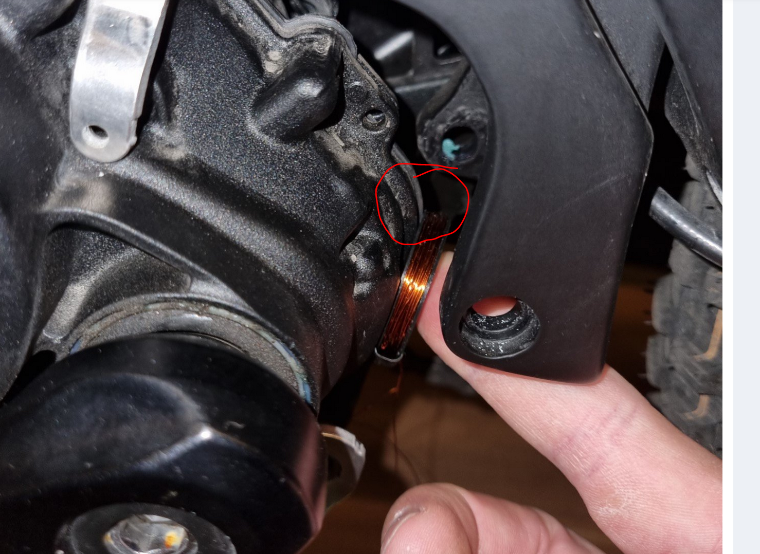
Hi Mervious,
First regarding the winding, 100 turns at 0.3mm giving 3.2ohm sounds exactly like mine. I've got a 6.6ohm resister in place to bring the total to ~11ohms. I think it's more the placement you need to perfect. Its not so much sensitive within 1mm, but looking at your photo, my coil is around 10mm higher than yours, see the snip attached.

I bend my coil so it straddles that circled lump in the motor case. Give that location a try?

Ps yes I noticed the same with the coil remaining powered on and put the same fix in, albeit for 2secs - but I never got around to uploading the updated code ;)

Capture.PNG
 

megabobra

Active member
Jul 24, 2022
266
268
Australia
Guys it's simple, Speedbox is not reliable and not working well with the Smart System

If you some a real chips who work well after X hundred KM without errors you need to look with the MTT Smart SP and SB : MTT SmartSP for Bosch Smart System 2022

You can read (translate obviously) the 100 pages of one the biggest German ebike forum it's the perfect solution!

sonstige(s) - Tuning für Bosch Smart System 2022 (keine Rechtsbeiträge u.ä., diese bitte nur in der Plauderecke, ansonsten gibt es Threadsperren)

Sadly as usual this one's not compatible with the rim magnet ;)
 

megabobra

Active member
Jul 24, 2022
266
268
Australia
Yes, the flow app was connected because I do have eBike Alarm enabled.
I disabled the app access to my position, and I'm not using any navigation by Bosch.

I'm genuinely very curious to know if this detection is related to the approach with the coil or if it was code related. Half of me wishes it was running the same code when it failed so we'd at least know its limit!

What's your plan now? Are you keeping it in place?
 

megabobra

Active member
Jul 24, 2022
266
268
Australia
My understanding is that PWM ports can output up to 5V, which ought to be enough for our coils there (especially the handmade ones) right ? Wouldn't rewiring the 5V pin of our coil to a PWM port just work ? (this is where I got that 5V output value from : How To Change the PWM Frequency Of Arduino Nano )
Yes it'll definitely do 5v but there's very little current behind it, only enough for an LED or two. However, it does look like a slightly different transistor does allow a proportional output: TIP120 Darlington Transistor

I'll investigate the use of this. It might be good upgrade to put in place to further reduce the detection risk.

EDIT: hmm looks like even the existing 2N2222A might work with this!
 
Last edited:

GBikeBoy

New Member
Jul 4, 2023
8
6
New York
Fully agree. Speedbox 1.0 doesn’t work. I have been advised by ebiketuner to use Volspeed instead.

Are there any bad experiences with that chip?
Guys it's simple, Speedbox is not reliable and not working well with the Smart System

If you some a real chips who work well after X hundred KM without errors you need to look with the MTT Smart SP and SB : MTT SmartSP for Bosch Smart System 2022

You can read (translate obviously) the 100 pages of one the biggest German ebike forum it's the perfect solution!

sonstige(s) - Tuning für Bosch Smart System 2022 (keine Rechtsbeiträge u.ä., diese bitte nur in der Plauderecke, ansonsten gibt es Threadsperren)
 

megabobra

Active member
Jul 24, 2022
266
268
Australia
Yes it'll definitely do 5v but there's very little current behind it, only enough for an LED or two. However, it does look like a slightly different transistor does allow a proportional output: TIP120 Darlington Transistor

I'll investigate the use of this. It might be good upgrade to put in place to further reduce the detection risk.

EDIT: hmm looks like even the existing 2N2222A might work with this!
OK final update on this. I'm not sure it'll be possible using the PWM output. This output is still digital, where it just adjusts the duty cycle (time spent on vs off) of that output in order to present a varying voltage. For example, for a 5v output pin, to achieve 2.5v output the duty cycle is set to 50%, meaning the power is cycled between 0v and 5vvery quickly with equal time spent at each voltage. For 4v, the duty cycle is 80%, so time spent at 5v is four times that spent at 0v, and so on. When powering something like an LED this works fine because the voltage change happens so quickly that the human eye cannot see it occurring, when really it actually turning off and on very quickly.

SO, applied the coil, I don't think this is practical as the point of ramping up/down the power was to more naturally mirror the standard magnet's sinusoidal behaviour. When in fact, using the PWM output in this way may create quite a spiky ramp up/down, which is probably more suspect to Bosch than just a stepped on/off signal!

Appreciate any thoughts on this but I don't think it's going to help us.
 

Koekie

Member
May 2, 2023
23
38
Antwerp, Belgium
Guys it's simple, Speedbox is not reliable and not working well with the Smart System

If you some a real chips who work well after X hundred KM without errors you need to look with the MTT Smart SP and SB : MTT SmartSP for Bosch Smart System 2022

You can read (translate obviously) the 100 pages of one the biggest German ebike forum it's the perfect solution!

sonstige(s) - Tuning für Bosch Smart System 2022 (keine Rechtsbeiträge u.ä., diese bitte nur in der Plauderecke, ansonsten gibt es Threadsperren)
On that German forum there is no talk on what to do with a rim magnet system.
 

Mervious

New Member
Jul 7, 2023
12
11
Finland
Hi Mervious,
First regarding the winding, 100 turns at 0.3mm giving 3.2ohm sounds exactly like mine. I've got a 6.6ohm resister in place to bring the total to ~11ohms. I think it's more the placement you need to perfect. Its not so much sensitive within 1mm, but looking at your photo, my coil is around 10mm higher than yours, see the snip attached.

I bend my coil so it straddles that circled lump in the motor case. Give that location a try?

Ps yes I noticed the same with the coil remaining powered on and put the same fix in, albeit for 2secs - but I never got around to uploading the updated code ;)

View attachment 119717
Thanks for the tip, but nothing came up from that location either. And yeah, 2 seconds is better than 5, I modified also my code for that 😁

I then did what I should have done a long time ago, measure the magnetic field strength. I plotted the rim magnet field at approx. where the motor is and this is what I got:

Rim magnet.jpg


So more or less 120 µT. I then plotted my own magnet with 200 turns and I got around 3000 µT lol. So 25 times more than the rim magnet gives. No wonder it didn't work. Well back to the 100 turn magnet. I plotted that also and it too was way too powerful at 8 ohm. Then few tries of different resistors and went with total resistance of 82 ohm (79 ohm resistor + 3 ohm from coil). That one gives out still over 120 µT of magnetic field and the bike seemed to like that! When I put that to the location you showed, everything seems to work very nicely. I also removed the printed coil "holder", now it looks like what you got. And that one is very energy efficient at 0,06 A or 0,33 W! No extra heat coming from this setup.

Now printing the case for it and then tomorrow trying it out in the field. Hopefully still works then 😁
 

megabobra

Active member
Jul 24, 2022
266
268
Australia
Thanks for the tip, but nothing came up from that location either. And yeah, 2 seconds is better than 5, I modified also my code for that 😁

I then did what I should have done a long time ago, measure the magnetic field strength. I plotted the rim magnet field at approx. where the motor is and this is what I got:

View attachment 119831

So more or less 120 µT. I then plotted my own magnet with 200 turns and I got around 3000 µT lol. So 25 times more than the rim magnet gives. No wonder it didn't work. Well back to the 100 turn magnet. I plotted that also and it too was way too powerful at 8 ohm. Then few tries of different resistors and went with total resistance of 82 ohm (79 ohm resistor + 3 ohm from coil). That one gives out still over 120 µT of magnetic field and the bike seemed to like that! When I put that to the location you showed, everything seems to work very nicely. I also removed the printed coil "holder", now it looks like what you got. And that one is very energy efficient at 0,06 A or 0,33 W! No extra heat coming from this setup.

Now printing the case for it and then tomorrow trying it out in the field. Hopefully still works then 😁
That's outstanding, thanks Mervious! I had tried to do this early on in the project but I only had my phone to take the measurement. Needless to say it wasn't accurate... and in fact whenever the reading was too high, it would somehow temporarily wreck the phone's magnetic sensor such that it just wouldn't take a reading at all again until the phone was restarted.

May I ask what you used to collect the data? I think there's more value in improving the target strength of the field rather than its ramp up/down shape. I'd be keen to spend a bit more time with you with some more measurements if you're able? 😎
 

Mervious

New Member
Jul 7, 2023
12
11
Finland
That's outstanding, thanks Mervious! I had tried to do this early on in the project but I only had my phone to take the measurement. Needless to say it wasn't accurate... and in fact whenever the reading was too high, it would somehow temporarily wreck the phone's magnetic sensor such that it just wouldn't take a reading at all again until the phone was restarted.

May I ask what you used to collect the data? I think there's more value in improving the target strength of the field rather than its ramp up/down shape. I'd be keen to spend a bit more time with you with some more measurements if you're able? 😎
Unfortunately the same way as you did, with a phone 😄 I wouldn't look too much at the absolute values, but more on the relative. I think it is accurate enough (Samsung Galaxy S21+) for that kind of work, especially to see if the magnetic field is 25x more than what is needed 😁 I used an app called "Physics Toolbox Magnetometer" to plot the values. I noticed that the live screen doesn't seem to keep up fully, better to plot and use excel. But never had any issues with the phone sensor like you did.

But indeed, these are not accurate values like what could be got with real tools.
 

megabobra

Active member
Jul 24, 2022
266
268
Australia
Unfortunately the same way as you did, with a phone 😄 I wouldn't look too much at the absolute values, but more on the relative. I think it is accurate enough (Samsung Galaxy S21+) for that kind of work, especially to see if the magnetic field is 25x more than what is needed 😁 I used an app called "Physics Toolbox Magnetometer" to plot the values. I noticed that the live screen doesn't seem to keep up fully, better to plot and use excel. But never had any issues with the phone sensor like you did.

But indeed, these are not accurate values like what could be got with real tools.
Terrific thanks. I'm using an S21, so I wonder if it was just the app I was using... I'll give it another try with the one you mentioned. Thanks for the tips!
 

Mervious

New Member
Jul 7, 2023
12
11
Finland
I had 8 km test ride today and everything worked nicely, just like planned! Now hopefully it will work in the future as well without any error messages. Thanks @megabobra for the idea for the electromagnet! Lot's more fun riding a bit faster than 25 km/h 😉
 

Poshisfat

New Member
Jul 11, 2023
1
0
Ramsgate, UK
Hey Guys,

Been lurking for a long time here and really hats off you @megabobra & @Koekie for what you've done.

Quick question as I am an absolute electrician newbie. I see that the Mega system is really suited for rim magnets and rotor magnets. @Sander mentioned to a few others with a spoke magnet (like myself) that the 3rd party chip systems are the way to go as the Mega is not for this type. But I fear the risk of the error buying this.

My Question:
Is there no way that the Mega can be jimmy rigged to fit the spoke magnet system?

It just seems like the Mega really is the most reliable way as you're simply changing the input to the sensor and not messing with any internal circuitry...Or is this just the sad truth where I must get a chip box and take a risk?

...Also anyone tried the new Volspeed V4 for Smart system that got released last month? Don't Volspeed tend to outperform Speedbox somewhat for previous motors?

Thank you again and appreciate the hard work you guys are doing for clueless hopefuls like myself.
-M
 

EMTB Forums

Since 2018

The World's largest electric mountain bike community.

559K
Messages
28,290
Members
Join Our Community

Latest articles


Top